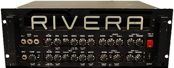
The RIVERA™ Tube Rack Series Stereo Amplifiers User Manual
TBR-1, TBR-2, TBR-3 (HAMMER™ 120), TBR-5 (HAMMER™ 320)
Contents
Safety Considerations and Warnings
WARNING: TO AVOID RISK OF SHOCK OR FIRE, DO NOT EXPOSE THIS AMPLIFIER TO RAIN OR MOISTURE. DO NOT REMOVE METAL COVERS OR CHASSIS PARTS REMOVING THE BOTTOM COVER EXPOSES EXTREMELY DANGEROUS HIGH VOLTAGES. NO USER SERVICEABLE PARTS INSIDE, HAZARDOUS VOLTAGES ARE PRESENT INSIDE CHASSIS. REFER ALL SERVICING TO QUALIFIED PERSONNEL
CAUTION: TO AVOID FIRE HAZARD, ALWAYS REPLACE FUSE WITH SAME TYPE AND RATING!
CAUTION: ALWAYS REPLACE LINE CORD (MAINS SUPPLY) WITH PROPER TYPE!
Always transport your amplifier securely, preferably in a suitable rack enclosure. Before operating your amplifier, be sure the speakers used are properly connected and the power amp impedance selector switches (on the rear panel) are set to the correct load impedance. For export markets where 220-240VAC is encountered, adjust the voltage selector before plugging into the mains power. If you are unsure of the voltage in your area, contact your local RIVERA dealer or importing distributor for information. For Japan 100VAC Models, all instructions for 120VAC models apply.
RIVERA products are handcrafted in the United States. In the event that you have any questions whatsoever on service, please contact us at (818) 833-7066, or write to us at Rivera Research and Development, 13310 Ralston Ave., Sylmar, CA 91342, USA. Telefacsimile: (818) 833-9656. Also if there are any suggestions or comments that you have for us regarding our products, please write to us.
TMEQ, PCOMP, FOCUS, POWER CLASS, and the RIVERA logo are registered trademarks of RIVERA Research and Development.
Strat is a registered trademark of Fender Musical Instruments.
Introduction
The challenge has always been to provide equipment that can deliver to an audience the sound a musician hears inside of his head. The challenge is made more difficult by the fact that each musician hears sound differently. This raises the question whether a single piece of equipment can ever be expected to realize the Inner expression of more than a handful of people. The TBR Series, carefully crafted amplifiers each with wide-ranging possibilities, can he viewed as part of our answer to that question.
The RIVERA TBR Tube Rack Series has been designed for the professional player who requires a rugged and versatile amplifier that occupies only four rack spaces. The components used in the circuitry meet the most stringent computer and military specifications.
Rivera Research and Development is heavily involved with musicians around the world, including leading session players In Hollywood. The design and construction of the TBR Series allow the player to utilize the latest in stereo effects devices and consolidate his entire system in a small and concise rack without giving up tube amplifier characteristics. It is the culmination of over 20 years of amplifier experience.
The Standard Models: TBR-1 and TBR-2
Channel 1 of the Standard Model contains exclusive RIVERA features such as PCOMP (Active Pickup Compensation), TMEQ (Tuneable Midrange Equalization), FOCUS (variable damping factor control), two completely Independent preamp channels, stereo effects loop, stereo power amps, and forced air cooling.
Channel 2 of the Standard, M, and SL Models is designed for clean rhythm. Sonically, it is in the same textural family
as the Fender 4×10 Bassman, old black-face Fender Twins, and early plexiglass-front Marshalls.
The M Models: TBR-1M and TBR-2M
The M Model is designed for musicians looking for a sweeter and fatter tone than the Standard Model TBR. With two additional equalization controls in Channel 1 than the Standard Model, the M Model offers more timbre possibilities. The trade-off is that the M Model has a little less dynamic attack, more compression, and is more easily driven into preamp distortion than the Standard Model. Sonically, the M Model is related to the traditional sweet tone of the Fender/Dumble/Boogie family. Channel 2 is the same as on the Standard Model.
The SL Models: TBR-1SL and TBR-25L
The Super Lead
Model is designed for the player desiring the ultimate heavy-metal crunch tone. It has the highest amount of gain of any of our models yet is still quiet enough to be used in the studio. The SL retains the tonal versatility of the M Model except that — due to differences in circuitry — the SL does not need the CONTOUR control. Sonically, the SL Model is related to the Marshall family, with the most sustain, compression, and distortion of the TBR Series. Channel 2 is the same as on the Standard Model.
The HAMMER™ Models: 120 (TBR-3) and 320 (TBR-5)
Designed for use as stand-alone power amps, the Hammer™ 120 and Hammer™ 320 use the same versatile power amp section as the rest of the TBR line-up. Although without preamps, the Hammer™ Models contain an extra gain stage that allows the amplifier to accept instrument-level input and still produce full power output. The Hammer™ Models do, of course, accept line level input as well.
Front Panel Features
Pickup Compensation (PCOMP) (TBR-1, TBR-2)
This exclusive RIVERA feature adjusts the sensitivity of the preamp section to match the output level of the pickups without changing their timbre. The PCOMP knob is labeled 1 thru 10. Position 4 is unity gain, meaning the output level is equal to the Input level. Position 10 is full boost, and position 1 is maximum attenuation.
Example 1. Weak single coils such as old Strats would require much more gain to achieve a pleasingly hot timbre than a modern rewound humbucker. The PCOMP setting would thus be between 8 and 10.
Example 2. Some super hot pickups can distort anything resembling an amp. These require reduced gain to sound clean, allowing both the true timbre of the pickup can be heard and differentiation among the Individual strings. The PCOMP setting would thus be between 2 and 4.
Example 3. The player using an Instrument equipped with humbucking pickups desires an outrageous hot timbre in CHANNEL 1 but when he switches to CHANNEL 2, he requires a slightly edgy lead timbre yet with a clean background. PCOMP would be assigned to CHANNEL 2, as CHANNEL 1 has an adequate amount of gain (with the MASTER knob pulled out).
CHANNEL 2 (VOLUME, TMEQ, and MASTER) would be adjusted in conjunction with the PCOMP knob to achieve the required edge. Example 4. The musician has a typical stock Strat and wants two different tonalities of a hot sound with thick sustain. PCOMP would be assigned to BOTH and adjusted to position 8 or 10, with CHANNEL 1 and CHANNEL 2 adjusted to taste for those timbres (most likely both MASTER and BRIGHT boosts would be pulled out).
PCOMP may be assigned to either or both channels of the amplifier using the ASSIGN switch to the right of the PCOMP control knob. This enables the musician to selectively boost or cut the normal gain in accordance with his wish to play anywhere from extra clean to extra distorted and sustained.
PCOMP can also be bypassed while still utilizing the SEND jacks for a buffered direct signal feed by pulling the PCOMP knob out (this also bypasses the PATCH bay RETURN jack).
Buffered Front Panel Patch Bay (TBR-1, TBR-2)
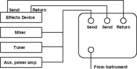
In addition to pickup gain matching and preamp overdrive setting, TBRs offer front panel access to a PATCH point, facilitating the connection of effects devices such as a compressor or limiter in the pre-preamp position. PCOMP serves as a buffer with variable gain In this configuration. Connect SEND to the in put of the effect and RETURN to the effect output at the front panel PATCH points.
There are in fact two pre-preamp SEND jacks, making it possible for the musician to run a buffered effects loop while at the same time running a direct sound
connection to a recording console, tuner, or other device requiring the direct signal of the instrument. The instrument is, of course, also buffered from any signal loss from the second send.
Example. If the musician requires a variable level direct signal (like a direct box signal split) for connection to a line Input of a recording console (potentially bypassing the mic preamp), with the instrument connected to the TBR-1 input lack the PCOMP knob would be pulled out, the console connected to send 1 or send 2 of the front panel patch bay, and the PCOMP knob adjusted for the proper output level. Even though the gain of the PCOMP is not affecting the TBR-1 preamp, the instrument’s signal is still buffered against impedance mismatches and improper loading between the TBR-I and the recording console.
Input Level Select (TBR-3, TBR-5)
The Hammer 120 and Hammer 320 power amplifiers allow you to match the amplifier input level to the output level of your equipment. In the High setting, the amplifier will handle signals up to +15dB. In the Normal setting, the amplifier is set for signals at 0dB. In the Low setting, the amplifier will accept signals as low as -10dB.
Example 1. You wish to run directly from your effects string Into the amplifier. Typically, effects-level devices (especially the Roland Boss Chorus) have only weak output signals. The Input Level Select setting would thus be Low.
Example 2. You wish to feed the amplifier from a preamp, mixing console, keyboard, or some other device that boosts the signal above instrument level. The Input Level Setting would thus be either Normal or High, depending on the output level of the device. Normally, you would set the Input Level Select to eliminate any distortion caused by a too-hot input signal.
Preamp Controls
TBR-1 is equipped with two different sounding channels, or, if you will, two different palettes of tonal color with which to paint. Each channel has a complete (although not identical) set of controls that is separate from those of the other channel. Channel selection is accomplished either by pressing the VOLUME control knob of CHANNEL 2 or by use of the channel selection FOOTSWITCH. To the left of each channel volume control is an LED (Light Emitting Diodes) indicator to show which channel is activated.
Channel One
CHANNEL 1 has a three-band passive timbre control network with variable slope for changing the frequencies and the Interaction of the controls. Slope variations affect the midrange notch.
Volume (All)
On the TBR-1 and TBR-2, the VOLUME control actually controls the volume in conjunction with the MASTER control. In traditional amplifiers, the volume control used In conjunction with a master control is more properly referred to as a gain control, as it controls the gain of the preamp section. In the TBR Series, however, preamp gain characteristics are set primarily through the PCOMP control, leaving preamp volume characteristics to the VOLUME control and power amplifier volume characteristics to the MASTER control. By separating these duties among three controls instead of between two controls, the TBR amplifier gives you more flexibility in honing your sound.
On the TBR-3 and TBR-5, the VOLUME control works alone to regulate amplifier output.
Treble (TBR-1, TBR-2)
The TREBLE control is a standard passive timbre control. (Standard Models)
The TREBLE control has the additional feature of a pull-out BRIGHT switch. Unlike most other amplifiers, however, the BRIGHT switch provides a nice shiny highlight to the sound instead of the normal screechy high boost.
(SL Models)
The TREBLE control can be pulled out for gain boost instead of treble boost. With the knob pulled out, the amplifier compresses the Instrument signal, slightly reducing the transient response. This masks the attack of the pick and gives more sustain. (Compare with the pull-gain on the BASS control.)
Slope (All)
Until Rivera Research and Development began its exploration into the inner workings of guitar amplifiers, most musicians were unaware of the existence of midrange notch in their amplifier’s frequency response, or of how modifying the notch would open up new worlds of sound for them. The SLOPE control was designed to exploit the behavior of the notch.
Settings of the SLOPE control vary from 1 to 5. In position 1, the notch is most deep, making the sound more thin in the midrange. This is the sound most often referred to as a pre-CBS
sound. As the control is turned upwards towards its maximum setting of 5, the notch is simultaneously filled in and moved lower in frequency. This has the effect of fattening up the sound, as well as giving the amplifier more overall gain.
Because the controls of channel 1 are passive they are interactive. When the SLOPE switch is at its maximum fat
position there is substantial midrange, and the BASS and MIDDLE controls are affected in their range. If the TREBLE control is on position 10 at this point, the effectiveness of the bass control seems less apparent. As the TREBLE control is turned down past position 6 or so, the bass control again becomes effective. Experimentation with the controls and their wide range of sounds and versatility will yield the best results.
Example 1. The user is playing an Instrument that has an excessively fat sound and requires a thinner timbre (absence of midrange). The SLOPE switch would be set at position 1, the MIDDLE control turned to I, TREBLE pulled out (for Bright timbre) set between 8 and 10, and BASS adjusted for taste (probably between 3 to 6).
Example 2. The musician is using a thin sounding guitar and needs more body on the top strings without boomy bass. The SLOPE switch would be set to position 3 to 5, TREBLE set 6 to 10, BASS set 5 to 10, and MIDDLE on 10.
Middle (TBR-1, TBR-2)
The MIDDLE control is a standard passive timbre control. As noted above, as the SLOPE control setting approaches S the effect of the MIDDLE control is reduced.
(M and SL Models)
The MIDDLE control has a PULL FOR NOTCH SHIFT position. A notch
in this case is a dip in the frequency response. When the control is pushed in, the notch point is at 550 Hz. This is a very warm and fat sound typically associated with British amplifiers, and it is especially great for Instruments with single-coil pickups. When the control is pulled out, the notch is shifted to 250 Hz. This provides a good rhythm sound typically associated with American amplifiers, and It is great for instruments with humbucking pickups.
Bass (TBR-1, TBR-2)
The BASS control is a standard passive timbre control. As noted above, as the SLOPE control setting approaches S the effect of the BASS control is reduced.
(M Models)
The BASS control has a PULL FOR CONTOUR position. This provides equalization after the master volume control for bass boost that lends additional warmth at low levels, compresses the midrange slightly, and increases the highs slightly for a little extra sparkle, as might be needed for rhythm tone enhancement.
(SL Models)
The BASS control can be pulled out for gain boost instead of contour adjustment. With the knob pulled out, the amplifier gain Increases, making it easier to achieve distortion. (Compare with the pull-gain on the TREBLE control.)
Master (TBR-1, TBR-2)
The MASTER control regulates the amount of the power amplifier boosts the signal it receives from the preamp section of the amplifier.
(Standard and M Models)
Preamp gain can be augmented by pulling out the MASTER control. The gain achieved this way is separate from the gain achieved via the PCOMP control.
(SL Models)
No pull function.
Channel Two
CHANNEL 2 has a two-band passive timbre control network and one band of active TMEQ (Tuneable Midrange Equalization), with five different frequencies of selective midrange boost, 250Hz, 500Hz, 750Hz, 1kHz, and 1.25kHz.
CHANNEL 2 has a different range of gain compared to CHANNEL 1 and possesses more headroom. This makes CHANNEL 2 ideally suited for maximum dean playing. If a crunchy texture is required at low levels, the MASTER can be pulled out for more gain and PCOMP used for whatever additional gain is required to make the desired crunch.
Volume (TBR-1, TBR-2)
The VOLUME control regulates preamp volume, as described above in the section on the CHANNEL 1 VOLUME control. The CHANNEL 2 VOLUME control also features a momentary contact switch with which to change back and forth between CHANNEL 1 and CHANNEL 2.
Treble (TBR-1, TBR-2)
The TREBLE control is a passive timbre control incorporating a BRIGHT boost, as described above in the section on CHANNEL 1 TREBLE control.
TMEQ (TBR-1, TBR-2)
TMEQ is a quasi-parametric equalizer that allows independent (that is, no interaction with the BASS and TREBLE controls) selective frequency boost to accentuate different frequency points. TMEQ is used to manipulate the midrange notch that falls between the effective range of the BASS and TREBLE controls. Using TMEQ, it is possible to both move this notch and to make it shallower or deeper.
Frequency
The FREQUENCY control allows you to select which of the five available frequencies will serve as the center of the notch. Position one corresponds to 1.25kHz, position two to 1kHz, position 3 to 750Hz, position four to 500Hz, and position five to 250Hz. Position one has a thinner sound than position five.
Level
The LEVEL control varies the intensity of the notch, so that at the minimum setting of 1 the notch is at its deepest and at the maximum setting of 10 the notch is at its shallowest. Bass (TBR-1, TBR-2)
Bass
The BASS control is a standard passive timbre control. The BASS control also incorporates a switch that gives TMEQ additional effectiveness. With the BASS control in its normal (in) position, the notch is relatively deep. With the BASS control In the EXPAND (out) position, the notch emphasis is lessened, so that the mid band frequencies are more effected by TMEQ. This is particularly helpful when the amplifier is in overdrive.
Master (TBR-1, TBR-2)
The MASTER control regulates the amount of amplification given to the preamp signal by the power section of the amplifier. Additionally, preamp gain can be augmented by pushing in the MASTER control. The gain achieved this way is separate from the gain achieved via the PCOMP control.
Example 1. A player desires a slight wah
timbre yet fat and with an decent amount of drive and sustain using a Strat. TMEQ FREQUENCY would be set on position 3 or 4, TMEQ LEVEL between 7 and 10, TREBLE on 8, and BASS between 4 and 6. The MASTER would be pulled out and set to the desired loudness, and the VOLUME control would be set between 7 and 10, with PCOMP ASSIGN set to 2 and adjusted for desired crunch.
Example 2. A musician wishes to have a perfect comping timbre with a fat-sounding guitar such as a Gibson 335. TMEQ LEVEL would be set on 1, TMEQ FREQUENCY positioned between 1-3, TREBLE on 8, BRIGHT switch pulled out, BASS set between 3 and 5, VOLUME on 4, MASTER set between 8 and 10, PCOMP ASSIGN set to 2, and PCOMP level set between 3 and 5.
Reverb (TBR-1, TBR-2)
TBR-1 has a special internal Hammond Spring
reverb feature. The circuitry as well as the reverb pan design has been created for a pleasing and classic reverb sound: Midrange and upper midrange response is emphasized, while bass and treble response has been rolled off slightly to provide a clean and intelligible reverb effect.
Each channel is equipped with an individual reverb level control. Reverb may be turned on by pressing the CHANNEL 2 REVERB control, or by the pressing the appropriate footswitch button. Adjust the reverb settings to taste. An LED indicator shows the on/off status.
Footswitch Channel Switching (TBR-1, TBR-2)
In addition to manual channel switching via the CHANNEL 2 VOLUME control, the FS-1 FOOTSWITCH controls channel switching, reverb switching, and effects loop switching.
Effects Loop (TBR-1, TBR-2)
The active effects loop has a front panel SEND level control and the two RETURN level controls, one for each power amplifier. The SEND control is used to tailor the output of the TBR-1 and TBR-2 to the sensitivity of the first device in the effects loop, ideally providing enough signal level to keep the signal-to-noise level low while preventing overload of the input section of the effects device. The RETURN controls (A and B) are most commonly used to balance the return signals of two different effects loops, although they can also be used create differences in signal level for special effect. The three-position EFFECTS ASSIGN switch applies the effects to either or both channels. The effects loop can be turned on either by pressing the RETURN B control or by the FOOTSWITCH. An LED indicator shows on/off status. The SEND and RETURN jacks are located on the rear panel.
The rear panel SEND jack is always active and may be used as a continuous and variable preamp output, using the front panel SEND knob to control the output level. This signal is post-reverb and post master volume. Because the effects loop of the TBR-1 and TBR-2 is active, it is able to drive low input impedance effects devices, as well as return from high or low output source impedance effects pedals. Certain effects such as compressors are best used in line with the instrument. When using these effects, first try using the PCOMP PATCH point. The versatility of the TBR-1 and TBR-2 effects loop can be seen In the many ways of connecting it to external effects:
Stereo Effects
The rear panel SEND jack is connected to the input of the effects device or effects chain used. The rear panel RETURN A jack, which is controlled by the front panel RETURN A knob and feeds power amp A, is connected to one of the outputs of the effect or effects chain used. The rear panel RETURN B jack, which is controlled by the front panel RETURN B knob and feeds power amp B, is connected to the other output of the effect or effects chain used.
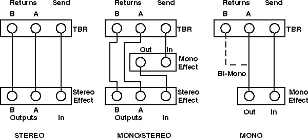
Monaural Effects
The rear panel SEND jack is connected to the input of the effects device or effects chain used. The rear panel RETURN A jack, which is controlled by the front panel RETURN A knob and feeds power amp A, is connected to one of the outputs of the effect or effects chain used. This will automatically give you the effects to both power amps. The effects loop level controls will adjust the level for their respective power amps, although the signal going to both power amps will be identical in content.
Bi-Monaural Effects
For straight signal from one power amp and effects signal from the other, connect the output of the effect or effects chain to the rear panel RETURN B lack. This is a very effective way of utilizing monaural pedal effects such as chorus, phaser, flanger, etc., and achieving a pseudo-stereo
effect, i.e. delay in one speaker and direct sound in the other, which gives aurally to the listener a stereo
effect.
Special Effects
The flexibility of the TBR-1 and TBR-2 can be further increased by using the effects loops without any effects plugged In at all.
When no cables are connected to the TBR effects loop jacks, signal from the effects SEND jack is sent directly to the effects return jacks. By turning the effects loop on, the effects loop send and return controls will be able to regulate amplifier volume. The most common use of this is to turn up the front panel VOLUME and MASTER controls to get the sound you want, then set amplifier volume using the effects loop send and return controls.
Note that for this to work, there must be nothing plugged into the effects RETURN jacks.
Adjusting the Effect Loop Level Controls
Some effects devices require line level for optimum signal-to-noise ratio. Other devices have less headroom and require instrument-level signal, and will distort easily with line-level signals. With either of these two types of device, however, the SEND control is adjusted so the level is at the maximum point before It overloads the effect or effects chain being used. Before setting the EFFECTS SEND level, adjust the preamp controls on both channels to desired settings. On the louder channel (if effects are desired), turn on the effects loop and adjust the SEND level to match your effect or effects chain. If your effects are equipped with level indicators, set the SEND level so that the effects device is just below the threshold of clipping. Adjust the two RETURN level controls (A and B) so that when the loop is turned on and off there is a proper level, and that the power amps are properly balanced.
If your effects chain includes a mix of instrument- and line-level effects, you will need to put the instrument-level units last in the chain (which means that the line level effects must have output level controls). Set the SEND level to match your line-level effects, adjust the output level of the last line-level effect In the chain to match the Input headroom of your first instrument-level effect. If this effects order is not satisfactory, you will need a buffer with gain control to step up the signal level from the output of the Instrument-level effects devices to match the input level requirements of the line-level devices.
FOCUS Control (All)
Each power amp channel is equipped with a FOCUS control. The FOCUS control allows adjustment of speaker cone damping. Damping is the ability of the amplifier to control speaker movement. The greater the control (high damping), the closer the movement of the speaker will follow the output waveform from the power amp. The less damping there is, the less control the amplifier has over speaker movement, resulting in speaker movement not directly caused by the output waveform of the power amplifier. Low FOCUS settings (1 through 4) tighten up the sound, while higher FOCUS settings (S through 10) loosen the sound.
The FOCUS control can be used to change the timbre from cold and dry (settings 1 through 4) to warmer with more sparkle (settings S through 10). The FOCUS control also allows you to compensate for room acoustics, or to get your sound
even when playing through borrowed speakers. For example, closed-back cabinets often have a tighter sound than open-back cabinets. When using one, the FOCUS control lets you more closely approximate the sound of the other.
Presence Control (All)
On the TBR-1 and TBR-2, the PRESENCE control affects power amp equalization, and behaves like a final bright control. Because it is after the preamp section of TBR-1, any distortion created in the preamp (in conjunction with the MASTER, gain BOOST, VOLUME, etc.), will have Its harmonics enhanced by the PRESENCE control.
On the TBR-3 and TBR-S, the PRESENCE control adjusts the high harmonic gain balance of the preamp section. It allows for shiny highs without an increase in distortion.
Power Switch (All)
The POWER switch is for turning the amplifier on and off. It connects the circuitry of TBR-1 to the mains. It is illuminated, and switches both the neutral and the line sides of the mains.
Standby Switch (All)
The illuminated STANDBY switch turns on and off the high (B+ or HT) voltage supplied to the power output tubes. By turning the POWER on and STANDBY off, you can warm up the amplifier before applying full voltage. This helps the tubes live longer. Tube life will also be extended if, during breaks, the STANDBY switch is used to turn the amplifier off
in stead of the POWER switch. This keeps the tubes at a more constant temperature, eliminating the thermal cycling that accelerates aging in tubes, and maintains the amplifier in a constant state of readiness.
On TBR products with serial numbers above 81500, the STANDBY switch affects only the power output tubes. This allows you to put your amp on standby and continue to use the preamp section, including the SEND jack of the effects loop.
TBR-1
The STANDBY switch has three positions. In the center position, the amplifier is on standby. In the down position, the amplifier is In the low-power mode. In the up position, the amplifier is in the high-power mode. You may switch from the low-power mode to the high-power mode at any time. This switch combines with the POWER CLASS switch on the rear panel to give you four distinct power levels. For more information on the POWER CLASS switch, see Rear Panel Features.
For more Information on available power levels, see the power level chart on the specifications page.
TBR-2
The STANDBY switch has two positions. In one position, the amplifier is on standby; in the other position, full voltage is applied to the tubes.
TBR-3, TBR-5
The TBR-3 and TBR-5 are both fitted with three STANDBY switches; two CHANNEL STANDBY switches and one MASTER STANDBY switch. Each CHANNEL STANDBY switch governs only one power amp (on the TBR-1 It governs both power amps).
The MASTER STANDBY switch places both power amplifiers on standby simultaneously. This is provided as a convenience so you do not have to individually place each power amp on standby unless you wish to.
Rear Panel Features
Mains Supply Power Connector (All)
This is for connection to an appropriate power cord (supplied) which has an IEC female plug on one end and a male mains plug on the other end. This cord is supplied specifically to accommodate the different safety and electrical code requirements of individual countries. Be sure to use a grounded electrical mains socket whenever possible. This type has a grounding pin in addition to the normal line and neutral pin. The power cord supplied with your unit has a 3-pin type plug. Do not cut off or damage the ground pin. If the available electrical outlet is of the older 2-pin type, please use a suitable ground lift adapter. USA, Canada, and Japan share a common CSA/UL style cord. Most of Europe and Scandinavia utilize a Euro plug and have a SEMKO/VDE style cord. Australia uses a different style plug. England also has its own plug. In the event that the power cord requires replacement, PLEASE REPLACE WITH SAME TYPE POWER CORD. Consult your RIVERA dealer for further information.
Mains Fuses (All)
These fuses protect your amplifier from damage due to shorts, momentary surges, and defective power tubes. In the event of fuse failure, PLEASE REPLACE WITH SAME TYPE FUSE.
If your fuse repeatedly blows, please refer your amp to your local RIVERA dealer or contact us at (818) 833-7066 for further service assistance.
| Model | 100V, 120V | 220V* |
|---|---|---|
| TBR-1, TBR-3 | 3AG 4 Amp 4 Amp Slo-Blo |
T2A 2 Amp Slo-Blo |
| TBR-2, TBR-5 | 3AG 8 Amp 8 Amp Slo-Blo |
T4A 4 Amp Slo-Blo |
* 5×20mm
Ground Polarity Switch (All 100/120V models)
(100VAC and 120VAC models only.) The ground polarity switch is for selecting a low current chassis ground (earth) alternative as a means of reducing grounding-related hum noise. Use the position that sounds the most quiet.
When using the TBR In combination with other amplifiers or electrical appliances in the same rack, or In a situation where a signal cord goes to and/or from the TBR and another mains-connected amplifier or appliance/chassis, and they are also equipped with polarity switches, switch them to the center position if possible, and use the GROUND POLARITY switch on TBR in the position that sounds most quiet. In the event that there is a ground loop hum due to redundant mains grounds (where more than one amplifier/appliance/chassis are connected to each other in some manner, and each unit in question has a mains/AC ground connection), try using ground lift adapters on the other units on a one-by-one basis until the hum is reduced. If this does not help, consult your local RIVERA dealer or contact the RIVERA factory for further assistance.
Mains Voltage Selector (All 220V models)
BEFORE ADJUSTING, PLEASE BE SURE THIS UNIT IS DISCONNECTED FROM THE MAINS SUPPLY AND THE UNIT IS SWITCHED OFF. CONSULT YOUR LOCAL ELECTRICAL AUTHORITIES FOR MAINS VOLTAGE INFORMATION IN YOUR AREA.
This feature is in place of the POLARITY switch for export markets. It allows the amplifier to be switched for 220VAC or 240VAC 5O/6OHz mains voltages.
For England, Australia, and any country where the mains voltage is 230-250VAC, please select the 240VAC position. For most of Europe and Scandinavia where the mains voltage is 210-220VAC, please select the 220VAC position. In some countries, 127VAC in encountered. In this case, use a 120VAC version of TBR. If your local voltages are none of the above, please contact us at the RIVERA factory for further assistance.
B+ Indicator Lamps and Fuses (TBR-2, TBR-5)
For the TBR-2 and TBR-5, each power amplifier channel has its own fuse for protecting the output section from short circuits and transient current peaks that exceed the normal current draw. These conditions are usually caused by a bad tube.
When a short circuit or transient peak causes the fuse to blow, the indicator lamp next to the blown fuse will show where the problem is.
| Model | 100V, 120V | 220V* |
|---|---|---|
| TBR-2, TBR-5 | T1A 3AG |
T1A |
*5×20mm
Impedance Selector Switches (All)
BEFORE PLUGGING IN SPEAKERS AND TURNING ON THE AMPLIFIER, PLEASE ADJUST THE IMPEDANCE SELECTOR SWITCHES TO PROPER IMPEDANCE LOAD SETTING.
Each power amplifier is equipped with an IMPEDANCE SELECTOR switch. This allows the amplifier to properly match the load of the speaker(s) being used, so that full output power is available at any one of the three load impedance settings (4, 8, and 16 Ohms). Please set the switch for the total impedance load of both speaker jacks combined. It is perfectly fine to set one IMPEDANCE SELECTOR switch at one impedance to match one set of speakers and the other IMPEDANCE SELECTOR switch at another impedance to match another set of speakers.
RIVERA speaker cabinets are equipped with 8 Ohm speakers (either stock British, or optional JBL or EV speakers) and are wired for either stereo or mono operation.
| Speaker Cabinet | Wiring | Mono | Stereo |
|---|---|---|---|
| RRD 2×10 extension | Parallel | 4 Ohms | 8 Ohms |
| RRD 2×12 Q-Cab | Parallel | 4 Ohms | 8 Ohms |
| RRD 4×10 extension | Series/parallel | 8 Ohms | 4 Ohms |
| RRD 4×12 stack | Series/parallel | 8 Ohms | 4 Ohms |
| Marshall 4×12 | Series/parallel | 16 Ohms | NA |
When using two Marshall 4×12 cabinets on the same power amplifier (one in SPEAKER 1 and the other in SPEAKER 2), the load is 8 Ohms and the IMPEDANCE SELECTOR should be set accordingly.
Most single speakers are 8 Ohms. If two of them are connected to the same power amplifier (one in SPEAKER 1 and the other in SPEAKER 2), the selector should be set at 4 Ohms.
POWER CLASS Switch (All)
The POWER CLASS switch allows you to change the fundamental tonal characteristics of your amplifier by actually changing the way the signal flows through the amplifier. Hi-fi enthusiasts have long known the differences among amplifiers that are based on the amplifier’s circuitry. Part of the reason a Fender sounds different than a Marshall is the way the signal flows through the amplifier. Usually when you buy an amplifier you are stuck with whichever circuit the designer decided on.
With the TBR Series, you have a choice between the higher power pentode class (also known as Class AB) and the lower power triode class (also known as Class A). The POWER CLASS switch works in conjunction with the three-position STANDBY switch in TBR-1, the Hammer 120, and Hammer 320 power amps to give you four distinct power levels. In the TBR-2, the POWER CLASS switch gives you two distinct power levels, along with their correspondingly different tonal characteristics.
The POWER CLASS switch is not primarily designed as a means of changing the power output of the amplifier, however. Its main purpose is to change the tonal characteristics of the amplifier in ways that timbre controls cannot. In the pentode mode, the sound is bright and edgy. In the triode mode, sound is sweet and silky. These changes have to do only with the difference in the way the amplifier processes the signal from your instrument in the power amp stage, therefore your front-panel timbre controls function the same under either power class setting.
For more information on the STANDBY switch, see Front Panel Features.
For more information on available power levels, see the power level chart on the Specifications page.
Speaker Output Jacks (All)
Each power amp is equipped with two speaker jacks. Both SPEAKER 1 jacks are equipped with an internal safety switch which turns the power amp off if no speaker plug is inserted. This means that in order to activate the power amp, you must use the SPEAKER 1 jack first. Each SPEAKER 2 jack is connected in parallel to its corresponding SPEAKER 1 lack.
(TBR-1, TBR-2)
When the effects loop is off, the preamp feeds both power amplifiers the same signal.
When the effects loop is turn on, each channel of the effects loop return feeds its own power amplifier. See the section on effects loops for more information about regulating amplifier volume using the effects loop send and return controls.
Direct Out jacks (All)
Each power amp is also equipped with a DIRECT OUT jack. This signal is capable of up to line-level output and is padded down from the speaker signal. It is low impedance, and is suitable for connection to PA mixers, tape recorders, and other power amps. If the amp is on standby or the SPEAKER 1 jacks are not used, the DIRECT OUT jacks are inoperative.
Direct Out Level Control (All)
The DIRECT OUT LEVEL control allows adjustment of the direct out level for matching the input requirements of studio and recording equipment, and slave amplifiers.
Effects Loop Send, Return A, and Return B Jacks (TBR-1, TBR-2)
The effects loop jacks are located near the center of the chassis. For further information please consult the section on effects loops above.
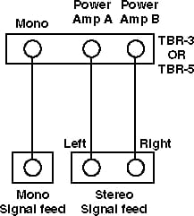
Power Amp Input jacks (TBR-3, TBR-5)
Instrument or line-level signals can be fed directly into the TBR-3 and TBR-5 through jacks on the back panel. Monaural signal feeds should be connected to the MONO jack when you want both amplifiers to receive the same input signal.
Bi-monaural and stereo signal feeds should be connected to the POWER AMP A and POWER AMP B jacks in order to give each signal its own amplifier.
To run only one amplifier with a monaural signal, use only one of the power amp jacks.
Footswitch Jack (TBR-1, TBR-2)
The RIVERA FS-1 three-function illuminated footswitch (supplied) comes with a 5+ meter Mogami Superflexible shielded 8-conductor cable. The connectors are 8-pin Preh locking DIN plug/jack. The footswitch cable/plug can be connected to TBR by Inserting the plug into the TBR FOOTSWITCH jack and twisting the locking ring on the plug. Channel Switching, Reverb, and Effects Loop selection can be accomplished by pressing the respective switches. LED indicators, which correspond to their respective counterparts on the TBR front panel, indicate when a function has been turned on.
Fan (All)
TBR-1 and TBR-3 are supplied with a fan for forced air cooling. The TBR-2 and TBR-5 are fitted with dual fans and special cooling passages In the chassis. All fans are mounted with finger guards. These fans are CSA/UL approved units for 100VAC and 120VAC models. For 220/240VAC models, the fan is a SEMKO/VDE approved unit. In the event that the finger guard becomes excessively dirty, unplug the amplifier from the mains and wipe the dust from the finger guard using a soft rag.
Tips and Suggestions
Using the TBR-1 or TBR-2 as a Preamp Only
TBR-1 and TBR-2 are equipped with a special power amp protection circuit; when no plugs are inserted into the speaker jacks the power amps are in an effective standby state. This means that if you wanted to use TBR-1 or TBR-2 as a preamp only, you would take the preamp signal from the SEND jack of the effects loop and not plug anything Into the speaker jacks.
For TBR Series amplifiers with serial numbers greater than 81500, the effects send jack remains active even when the front panel STANDBY switch is in the standby position.
Optimizing the TBR-1 or TBR-2 for the Studio
The studio is a perfect setting for the TBR-1 or TBR-2. Here are some suggestions:
- Run the effects loop of the TBR-1 or TBR-2 through the patch bay for use with studio effects.
- Use a separate isolated patch bay for the speaker jacks of the TBR-1 or TBR-2, with a resistive load
normalled
at 8 Ohms, with TBR-1’s IMPEDANCE SELECTOR set appropriately.- WARNING: IF YOU HAVE A SPEAKER CORD PLUGGED INTO SPEAKER JACK #1 OF TBR-1 OR TBR-2, THE POWER AMPS ARE FULLY OPERATIONAL. DO NOT OPERATE TBR-1 OR TBR-2 WITHOUT A PROPER LOAD ON THE SPEAKER JACKS.
- Connect one of the PCOMP patch sends to the patch bay for direct instrument sounds.
- Have two single speaker enclosures in separate closets with mics.
- Run the DIRECT OUT to the patch bay for direct recording of attenuated power amp signal.
- On the DIRECT OUT it is best to roll off the frequency response after 8kHz.
- You can use the TBR-1 or TBR-2 as a slave through the studio effects by using the
normalled
load resistors, and then take the signal from the DIRECT OUT for the external patch bay effects feed. - Instead of only
micing
acoustic instruments, run a piezo feed from the instruments through your TBR-1 or TBR-2. The EQ section of CHANNEL 2 is very musical for acoustic instruments. If the piezo feed is not possible, use a mic through a Jensen transformer into the INPUT of TBR-1 or TBR-2. Balancing between the equalized TBR-1 or TBR-2 signal and the direct mic signal will be very pleasant. - Because the effects loop and speaker jacks are accessible through the patch bay, use the TBR-1 or TBR- 2 power amp section to run the monitor speakers with tube timbre characteristics.
- With the TBR-1 or TBR-2 located in the control room, It is possible to play while mixing and yet be able to tune the amp conveniently. The effects loop is now within easy access of all the professional effects devices in the studio.
- PCOMP can provide a hot enough signal to bypass the mic preamps of the mixing desk and go direct into the faders. You may now utilize the PCOMP PATCH point for studio effects pre-preamp.
Using the TBR-1 or TBR-2 in a Stereo Slaving System
WARNING: FREQUENT USE OF THE TBR-1 OR TBR-2 IN A SLAVING SYSTEM WILL RESULT IN INCREASED TUBE WEAR. ALSO, LOAD RESISTORS ARE REQUIRED TO DISSIPATE THE POWER OF TBR-1 OR TBR-2 AS HEAT. MOUNT LOAD RESISTORS ON A NON-FLAMMABLE SURFACE, PREFERABLY METAL AND PROPERLY GROUNDED.
DO NOT USE THE METAL PANELS OF TBR TO MOUNT THE RESISTORS.
ALLOW ADEQUATE VENTILATION FOR THE RESISTORS. DO NOT TOUCH THE RESISTORS WHILE AMP is IN USE: ALLOW ADEQUATE TIME FOR THE LOAD RESISTORS TO COOL. MAKE SURE ALL CABLES AND WIRE USED ARE OF TOP GRADE MATERIAL. MAKE SURE BEFORE TURNING ON THE SYSTEM THAT THE IMPEDANCE SELECTOR SWITCHES ARE SET FOR THE SAME VALUE AS THE LOAD RESISTORS, AND EVERY PART OF THE SYSTEM IS CONNECTED PROPERLY WITH ALL PATCH AND SPEAKER CABLES FULLY TESTED.
The concept of this system is to utilize the power amps of TBR-1 as distortion devices, with other higher wattage power amps (such as TBR-5) to power the speakers.
Connect the INPUT of the TBR-1 to the instrument. Connect the effects loop to any effects devices desired as part of the pre-power amp sound of the TBR-1. Connect the SPEAKER 1 jacks of power amp A and B to 250 Watt 8 Ohm load resistors (follow the warnings stated previously). Use the DIRECT OUT jacks to feed an effects switcher such as the Ibanez EPP-400, or the TC Electronic 2290. Note: this same procedure can be followed with the TBR-2 if you use 500 Watt resistors in place of the 250 Watt resistors, however, it is definitely not recommended.
Also, connect SEND 1 of PCOMP to other amplifiers that you wish to drive. The SEND of the TBR-1 or TBR-2 effect loops may be used as the alternate dean sound feed when run through the effects switcher. Connect TBR-5 to the effects switcher, or feed it with a line mixer or whatever you desire. You can use the slaved direct out to feed delay units, etc. For more information on this method, contact us at the factory.
Use of External Slave System as Effect
Use of another amplifier such as a cheap 10-Watt generic amp for a distortion effect is kind of the reverse of the previous system. There are two ways to accomplish this. One is to feed the input of the slaved amp with the SEND 1 of PCOMP, then use the line feed of the slaved amp to send to effects devices such as delay lines, flangers, etc., and then bring the output of that effects chain back Into the front panel PCOMP PATCH bay RETURN. This method gives you a distinct and separate lead timbre unaffected by the equalization and gain/distortion settings of the TBR-1 or TBR-2.
Cables and Cords
Signal cables such as patch cords and your guitar cord must be well shielded and of low capacitance. High capacitance cable will influence the harmonic content of your signal by serving as a low-pass filter. In other words, if your cables have too much capacitance, you will lose high end.
The cable shielding keeps the hot lead of the cable surrounded by grounds, lowering hum and interference noises. The center conductor of the cable must be quite flexible, and the outer covering should be rugged and impervious to the normal road hazards of feet, casters, oil, and miscellaneous torture.
Recently, Mogami of Japan has made available some excellent signal cable that it sells as part number W-2524. It is made of oxygen-free copper. It is very flexible, low capacitance, and free from microphonics. We highly recommend it. Belden also makes some adequate cable types. For more information, contact your local Mogami or Belden dealer, or if you are unable to find this cable contact us direct.
Speaker cables are also very critical. Never use a guitar signal cord for speakers. The resistance In your speaker cables can make substantial losses In the amount of amplifier power transferred to the speaker. Use a minimum of 16 gauge wire for lengths up to 3 meters, and 14 or 12 gauge for longer runs. Cable that uses neoprene as an outer insulation is superior to vinyl In standing up to abuse. An excellent choice is Mogami #W-8116 (16 Gauge) or #W-8112 12 Gauge).
The plugs to be used are also important. Basically there are only two manufacturers of phone plugs that are acceptable; Neutrik of Lichtenstein and Switchcraft of USA. In our opinion, Neutrik makes the better plug of the two. The Neutrik is sold as part number NP2C. Switch craft is sold as part number 470 for signal plugs and as part number 160 for speaker plugs.
For DIN plugs, Preh and Hirschmann of West Germany are the most renown. In England, however, the Futters company makes some excellent locking DIN plugs and jacks under the Deltron brand. If you are making MIDI cables, use good wire also, such as Mogami #W-2757.
Preparations for touring
When mounted in a proper rack cabinet, the TBR Series is well-suited for the road, so no special handling is required beyond that which you would extend to any valuable piece of electronic equipment. Because of the weight of the TBR components, we do recommend mounting your TBR at the bottom of your rack.
For extended touring, we recommend supporting the rear of the TBR chassis, especially the TBR-2 and TBR-5.
Suggested Settings
Note: += Control Out |
PCOMP | Vol | Treb | Slope | Mid | Bass | MV | Rev | FOCUS | Pres | |
|---|---|---|---|---|---|---|---|---|---|---|---|
| Clean Jazz | Ch. 1 | 3 | 3 | 9+ | 1 | 1 | 10 | 10 | 10 | 3 | |
| Splanky HB | Ch. 2 | 4 | 3 | 9+ | 1 | 1 | 10 | 10 | 10 | 3 | |
| Clean Jazz | Ch. 1 | 4 | 4 | 8+ | 3 | 1 | 10 | 10 | 10 | 3 | |
| Splanky Strat | Ch. 2 | 5 | 4 | 8+ | 5 | 5 | 10 | 10 | 10 | 3 | |
| Clean Jazz | Ch. 1 | 3 | 3 | 8 | 5 | 10 | 10 | 10 | 10 | 3 | |
| Fat Humbucker | Ch. 2 | 4 | 4 | 7 | 5 | 10 | 8 | 10 | 10 | 3 | |
| Clean Jazz | Ch. 1 | 3 | 3 | 8 | 5 | 10 | 10 | 10 | 10 | 3 | |
| Fat Strat | Ch. 2 | 4 | 4 | 7 | 5 | 10 | 8 | 10 | 10 | 3 | |
| Clean Country | Ch. 1 | 3 | 3 | 9 | 1 | 1 | 8 | 10 | 10 | 7 | |
| Humbucker | Ch. 2 | 3 | 4 | 9+ | 5 | 1 | 8 | 10 | 10 | 7 | |
| Hot Edgy Slick | Ch. 1 | 8 | 6 | 9+ | 3 | 1 | 10 | 3+ | 10 | 8 | |
| Lead Humbucker | Ch. 2 | 10 | 10 | 6+ | 1 | 7 | 5 | 4+ | 10 | 8 | |
| Lukather Lead | Ch. 1 | 8 | 8 | 9 | 3 | 5 | 3 | 7 | 10 | 5 | |
| Humbucker | Ch. 2 | 10 | 8 | 8 | 4 | 7 | 4 | 10 | 10 | 5 | |
| Lukather Lead | Ch. 1 | 10 | 10 | 9 | 3 | 5 | 3 | 7 | 10 | 5 | |
| Strat | Ch. 2 | 10 | 10 | 8 | 4 | 7 | 4 | 10 | 10 | 5 | |
| Heavy Metal | Ch. 1 | 7 | 10 | 9 | 4 | 1 | 10 | 3+ | 10 | 9 | |
| Chord Wash Hum. | Ch. 2 | 8 | 10 | 9 | 4 | 10 | 5+ | 3+ | 10 | 9 | |
| Heavy Metal | Ch. 1 | 10 | 10 | 8 | 5 | 5 | 10 | 3+ | 10 | 9 | |
| Chord Wash Str. | Ch. 2 | 10 | 10 | 9 | 5 | 10 | 5 | 3+ | 10 | 6 | |
| Brian Mayish | Ch. 1 | 7 | 10 | 7 | 5 | 10 | 10 | 4+ | 1 | 8 | |
| Ahh Timbre Hum. | Ch. 2 | 9 | 10 | 6 | 3 | 10 | 5+ | 4+ | 1 | 8 | |
| Duane Eddy | Ch. 1 | 4 | 4 | 10 | 1 | 4 | 10 | 10 | 7 | 10 | 7 |
| Humbucker | Ch. 2 | 4 | 3 | 10+ | 1 | 1 | 10 | 10 | 7 | 10 | 7 |
| Duane Eddy | Ch. 1 | 4 | 4 | 10 | 1 | 4 | 10 | 10 | 7 | 10 | 7 |
| Strat | Ch. 2 | 5 | 4 | 10 | 1 | 1 | 10 | 10 | 7 | 10 | 7 |
| Tim May Sweet | Ch. 1 | 3 | 10 | 5 | 3 | 7 | 8 | 3 | 5 | 7 | 6 |
| EMG Strat | Ch. 2 | 4 | 10 | 5 | 4 | 10 | 10 | 3+ | 5 | 7 | 6 |
| Jay Graydon | Ch. 1 | 7 | 10 | 6 | 4 | 5 | 5 | 3+ | 10 | 4 | |
PegStrat |
Ch. 2 | 8 | 10 | 7 | 4 | 4 | 10+ | 3+ | 7 | 4 | |
| Randy Rhoads | Ch. 1 | 10 | 10 | 8 | 3 | 1 | 1 | 4+ | 8 | 9 | |
| Humbucker | Ch. 2 | 10 | 10 | 7 | 2 | 7 | 5+ | 4+ | 1 | 10 | |
Note: += Control Out |
PCOMP | Vol | Treb | Slope | Mid | Bass | MV | Rev | FOCUS | Pres | ||
|---|---|---|---|---|---|---|---|---|---|---|---|---|
| Blackface Hot | Ch. 1 | 5 | 7 | 8 | 3 | 4+ | 3 | 4+ | 7 | 7 | 7 | |
| Blackface Twin | Ch. 2 | 3 | 3 | 8+ | 1 | 1 | 10 | 10 | 6 | 7 | 7 | |
| Sykes Distorted | Ch. 1 | 10 | 10 | 7 | 5 | 1 | 3+ | 3+ | 8 | 10 | 8 | |
| Sykes Clean | Ch. 2 | 4 | 4 | 7+ | 5 | 4 | 4 | 10 | 6 | 10 | 7 | |
| Plexi 60s | Ch. 1 | 6 | 4-8 | 8 | 2 | 5 | 6 | 10 | 6 | 8 | ||
| Plexi 60s | Ch. 2 | 1 | 7 | 6 | 5 | 6 | 4 | 7+ | 6 | 8 | ||
| Studio Comping | Ch. 1 | 3 | 4 | 7+ | 1 | 1+ | 7+ | 8 | 8 | 3 | 8 | |
| Studio Comping | Ch. 2 | 3 | 4 | 5+ | 1 | 1 | 5 | 10 | 7 | 10 | 8 | |
| Big Rhythm | Ch. 1 | 3 | 4 | 7+ | 1 | 3+ | 10 | 10 | 7 | 3 | 8 | |
| Big Rhythm | Ch. 2 | 3 | 4 | 6 | 5 | 1 | 7 | 10 | 7 | 1 | 6 | |
| Clean Country | Ch. 1 | 3 | 4 | 8+ | 1 | 1+ | 10 | 10 | 7 | 8 | 6 | |
| Clean Country | Ch. 2 | 3 | 5 | 8+ | 1 | 1 | 6 | 10 | 7 | 8 | 6 | |
| Woogie | Ch. 1 | 10 | 10 | 8+ | 1 | 1+ | 10+ | 3+ | 8 | 6 | 7 | |
| Woogie | Ch. 2 | 10 | 10 | 9 | 1 | 1 | 5+ | 5+ | 8 | 7 | 6 | |
Note: += Control Out |
PCOMP | Vol | Treb | Slope | Mid | Bass | MV | Rev | FOCUS | Pres | |
|---|---|---|---|---|---|---|---|---|---|---|---|
| Eric Massive | Ch. 1 | 8 | 10 | 6+ | 4 | 10+ | 7+ | 6.5 | 6 | 5 | 8 |
| Eric Bright | Ch. 2 | 5 | 6+ | 3 | 4 | 5 | 8 | 7 | 10 | 6 | |
| R. Schenker 1 | Ch. 1 | 9 | 10 | 4.5 | 4 | 6.5 | 10+ | 6 | 5 | 5 | 5 |
| R. Schenker 2 | Ch. 2 | 9 | 10 | 6 | 2 | 2 | 5+ | 4.5+ | 7 | 8 | 7 |
| Metal Country | Ch. 1 | 7.5 | 3 | 6.5 | 3 | 8+ | 8 | 6.5 | 5.5 | 4 | 8 |
| Deep Rhythm | Ch. 2 | 4 | 7+ | 5 | 0 | 8 | 8 | 7 | 10 | 6.5 | |
| Sykes Special | Ch. 1 | 9 | 10 | 7 | 1 | 3 | 10+ | 6 | 6 | 4.5 | 7 |
| ’71 Vintage | Ch. 2 | 9 | 10 | 5+ | 3 | 10 | 1+ | 4+ | 6 | 4.5 | 7 |
| Plexi Vintage 1 | Ch. 1 | 9 | 10 | 7+ | 1 | 1 | 10 | 6 | 5 | 5 | 4 |
| Plexi Vintage 2 | Ch. 2 | 10 | 10 | 9+ | 5 | 10 | 3+ | 5+ | 6 | 7 | 5 |
| Blackmore 1 | Ch. 1 | 8 | 10 | 6 | 1 | 1 | 10+ | 6 | 5 | 5 | 4 |
| Blackmore 2 | Ch. 2 | 8 | 10 | 7+ | 5 | 1 | 1+ | 5+ | 4 | 8 | 10 |
| British Studio | Ch. 1 | ||||||||||
| Ch. 2 | 9 | 10 | 5+ | 2 | 10 | 4+ | 4+ | 6 | 5 | 7 | |
| Single Coil | Ch. 1 | ||||||||||
| Ch. 2 | 10 | 10 | 5+ | 2 | 10 | 3+ | 5+ | 6 | 6 | 5 | |
| Lynch Mob | Ch. 1 | 10 | 10 | 7 | 2 | 3 | 10 | 6 | 6 | 10 | 6 |
| Ch. 2 | |||||||||||
Note: += Control Out |
PCOMP | Vol | Treb | Slope | Mid | Bass | MV | Rev | FOCUS | Pres | |
|---|---|---|---|---|---|---|---|---|---|---|---|
| Name | |||||||||||
| Ch. 1 | |||||||||||
| Ch. 2 | |||||||||||
| Name | |||||||||||
| Ch. 1 | |||||||||||
| Ch. 2 | |||||||||||
| Name | |||||||||||
| Ch. 1 | |||||||||||
| Ch. 2 | |||||||||||
| Name | |||||||||||
| Ch. 1 | |||||||||||
| Ch. 2 | |||||||||||
| Name | |||||||||||
| Ch. 1 | |||||||||||
| Ch. 2 | |||||||||||
| Name | |||||||||||
| Ch. 1 | |||||||||||
| Ch. 2 | |||||||||||
| Name | |||||||||||
| Ch. 1 | |||||||||||
| Ch. 2 | |||||||||||
| Name | |||||||||||
| Ch. 1 | |||||||||||
| Ch. 2 | |||||||||||
| Name | |||||||||||
| Ch. 1 | |||||||||||
| Ch. 2 | |||||||||||
| Name | |||||||||||
| Ch. 1 | |||||||||||
| Ch. 2 | |||||||||||
Interface of the TBR Series to other Rivera Products
RIVERA Data Interface, TBD
The TBD allows switching the footswitch functions from alternate switch function sources such as the TC Electronics 2290 or the Roland GP-8.
The TBD connects to the TBR-1 and TBR-2 via a footswitch jumper cable that runs from the TBD DIN connector to the TBR footswitch connector. By using patch cords, you may then connect to the remote output of the device to be interfaced with. The TBD is powered by the TBR unit.
Installation
Because of the weight of TBR Series, you should mount your TBR amplifier in the bottom of the rack. If you have an amplifier in the middle of the rack, we recommend making some sort of rear brace to help support the rear weight stress. Use Phillips-head screws for mounting with nylon finish washer to protect the front panel of the TBR.
If your rack has more than one device, mount an AC outlet strip (protected with an internal circuit breaker) in the back of your rack.
Keep the airflow near the back of the TBR unrestricted. It is vital to the cooling of the TBR that the rack enclosure is open in the back during operation so the internal fan(s) of the TBR can cool the amplifier properly.
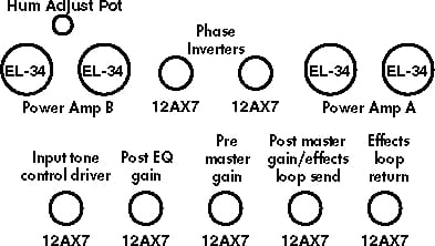
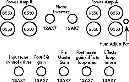
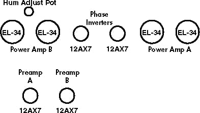
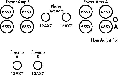
Tube Layouts
Maintenance
Each TBR has been designed and built with the professional musician in mind. The highest quality parts and materials have been used throughout this unit. In the unlikely event of a problem, some useful service information is provided.
REFER ALL SERVICING TO QUALIFIED PERSONNEL. NO USER SERVICEABLE PARTS INSIDE
CHASSIS. DO NOT REMOVE CHASSIS COVERS. HAZARDOUS VOLTAGES PRESENT INSIDE CHASSIS. THE FOLLOWING INFORMATION IS PROVIDED FOR THE BENEFIT OF QUALIFIED SERVICING PERSONNEL.
Spare Parts
Murphy’s law states that the parts you do not carry with you will be the ones you most need. Here is a list of recommended spare parts for the TBR Series:
4 — EL-34s TBR-1, TBR-3)
8 — 6550As (TBR-2, TBR-5)
5 — ECC83/7025/12AX7s (TBR-1, TBR-2)
3 — ECC83/7025/l2AX7s (TBR-3, TBR-5)
5 — Mains fuses (T4A, T2A) (TBR-1, TBR-3)
5 — Mains fuses (T8A, T4A, T1A) (TBR-2, TBR-5)
3 — T1A 5×20mm Fuses and 2 T1.6A
1 — Switchcraft/Preh 15CL8M Footswitch connector
Complete tool kit (with volt-Ohm meter)
Spare speakers for your cabinets (at least 1 for every 4 speakers you take).
Spare power, signal patch, and speaker cords
Spare fusepost extractor (in case you lose it in the dark replacing the mains fuse)
Tube Changes
It is normal for tubes to wear with age. The tubes and their function and physical location are shown on an accompanying chart. Tubes are accessible by removing the top cover. To remove the top cover, first remove the side Phillips screws, and carefully unplug the fan.
The power output tubes are selected by us for best performance. Substitute tubes are shown in the Bias Voltage chart. If 6550As (GE or Sylvania) are used in place of EL-34s, the power output will increase, but the timbre will be different.
The preamp and phase inverter tubes are 12AX7A/7025/ECC83/6681. All of these part numbers are for similar twin triode hi-mu miniature 9 pin tubes. We select these tubes for low hum noise, low microphonics, and high gain. Try to replace these tubes with the best you can buy.
A word about tube quality: There are only a handful of tube manufacturers worldwide, and there are no Western European or British companies manufacturing any longer. Marketing companies such as Groove Tube, Fender, and Mesa Boogie purchase their tubes from the same sources we do. Every tube you buy from us, whether in an amplifier or as a replacement part, has been thermally and electronically cycled for at least 12 hours. After this burn-in period, tubes that fail to meet our rigid specifications are either discarded or sold to other shops. If you wish to purchase replacement tubes from us directly, we will be pleased to assist you. Contact the factory for price and ordering information.
Warning: Never ever use Chinese EL-34s, 6550s, or 6L6GCs. They are mechanically unstable and will shorten the life of your amplifier.
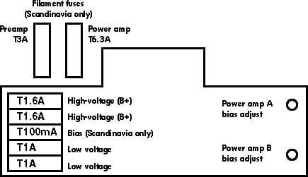
Bias Voltages
On the power supply/power amp printed circuit board there is a bias adjustment trim potentiometer for each power amp. To access the insides of the amplifier, remove the Phillips screw that hold the bottom panel.
NOTE: Removing the bottom cover exposes extremely dangerous high voltages.
If there is not enough adjustment in the range of the bias adjustment pot, you will have to change the resistors in the bias circuit to give you the proper bias voltage.
| Model | Tube | Bias |
|---|---|---|
| TBR-1, TBR-3 | 6CA7 | -39VDC |
| 6L6GC | -45VDC | |
| 6550A | -52VDC | |
| EL-34 (American) | -39VDC | |
| EL-34 (English or German) | -37VDC | |
| KT-77 | -39VDC | |
| TBR-2, TBR-5 | 6CA7 | -39VDC |
| 6L6GC | -49VDC | |
| 6550A | -54VDC | |
| EL-34 (American) | -41VDC | |
| EL-34 (English or German) | -39VDC | |
| KT-77 | -39VDC |
Measure bias with amplifier at idle, with nominal line voltage. Never use Chinese EL-34s, 6550s, or 6L6GCs.
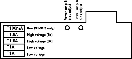
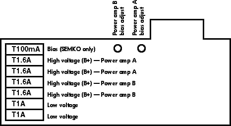
Internal Fuses
On the power amp/power supply circuit board, there are four or five printed circuit mounted fuseholders with 5×20 fuses. B+ fuses are T1.6A Slo-Blo, the low voltage fuses are T1A. The bias supply fuse is supplied only to Scandinavian markets and is T100mA. Also, for Scandinavia models, are two filament fuses mounted on the chassis. The fuses for both the power amp and the preamp are T8As.
PLEASE REPLACE FUSE WITH SAME TYPE, DO NOT USE HIGHER CURRENT VALUE FUSES.
Fuses normally blow for a reason. If one or both of the B+ fuses blows, this is probably caused by a shorted output tube. You should change the tubes as a precaution. See the accompanying diagram for location of fuses on the power amp printed circuit board.
Miscellaneous
The power output stage has protection devices on the output transformer. These devices assist TBRs in coping with open loads and temporary transients.
There are two preamp printed circuit boards. One with the tubes mounted on it, and another one with the PCOMP, logic, reverb, and TMEQ. All ICs are mounted on sockets. All LEDS are driven by transistors and each LED has its own current limiting resistor.
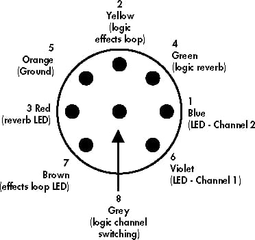
The footswitch circuit has low current, one shot Schmitt Trigger inputs, and all are latched. The switches are momentary contact, and are normally open. Each LED has its own return line, and this line can function for parity if necessary. Ground is common for all. See the accompanying diagram for the pin out of the footswitch connector. Maximum recommended footswitch cable length is 25 meters. Use Mogami #W-2789 for footswitch, patch, or extension cables.
Channel switching (in the audio path) is accomplished with optically coupled devices. Reverb is switched by a special high-voltage JFET analog switch. The effects loop is switched by a latched microminiature, military-grade relay, with full (zero Ohm) bypass on the effects loop returns.
The primary filter capacitors for all power supply circuits are 105 degrees Celsius military grade. All internal hookup wire used for point-to-point connections is a minimum 105 degrees Celsius 600V. Most signal conducting wires are of the shielded type. All large electronic components are glued to the circuit boards with a special vinyl adhesive. If in the unlikely case that any of the components need replacing, please use 3M Weather Strip Adhesive to affix the components to the printed circuit board. DO NOT use silicone sealants as they will eventually cause failure of soldered electrical connections.
Because we took great pains to choose and utilize the best parts we can find, please utilize original RIVERA spare parts whenever possible.
TBR Series Specifications
Preamplifier Section
Input impedance: greater than or equal to lOOK Ohm (TBR-1, TBR-2); greater than or equal to 47K Ohms (TBR-3, TBR-5)
PCOMP input impedance: greater than or equal to 1 Meg Ohm
PCOMP send impedance: less than or equal to 600 Ohms
Channel 1 EQ: 3 band passive with variable slope and bright switch
Channel 2 EQ: 2 band passive with one band of TMEQ (active) with variable frequency and gain, with expand and bright switch
PCOMP max. input level: greater than or equal to +10dBV
PCOMP return impedance: greater than or equal to 1 Meg Ohm
Tubes: ECC83/6681/7025
Switching logic: CMOS
Data/logic interface: Footswitch, front panel switches, or optional MIDI interface
Reverb: Both channels, Accutronics with special current source driver.
Channels: Selectable
Effects Loop
Assignability: Either or both channels
Controls: Individual send and return (×2) levels. Assign switch
Send impedance: less than or equal to 600 Ohms
Send level max: +30dBV
Return impedance (×2): greater than or equal to 250k Ohm
Return signal level max: +30dBV
Power Amplifier Section (×2)
Output impedance: Selectable 4, 8, 16 Ohm
Output tubes: Selected EL-34s (TBR-1, TBR-3) selected 6550As (TBR-2, TBR-5)
Damping factor: Variable
Speaker Jacks: 2 in parallel
Line out Impedance: less than or equal to 330 Ohms
Phase inverter: ECC83/6681/7025
Controls: Presence and FOCUS
| Model | Pentode class: High | Pentode class: Low | Triode class: High | Triode class: Low |
|---|---|---|---|---|
| TBR-1, TBR-3 | 60 | 15 | 30 | 8 |
| TBR-2 | 160 | n/a | 70 | n/a |
| TBR-5 | 160 | 45 | 70 | 20 |
Mains Power Requirements
CSA North American model: 120VAC 50/60Hz
MITI Japan model: 100VAC 50/60Hz
SEMKO/VDE/AUSTRALIA model: 220/240VAC 50/60Hz
Power consumption: greater than or equal to 150 Watts idle, 400 Watts full power (TBR-1, TBR-3), greater than or equal to 240 Watts idle, 700 Watts full power (TBR-2, TBR-5)
General
Weight: greater than or equal to 50 lbs. (TBR-1, TBR-3); greater than or equal to 68 lbs. (TBR-2, TBR-5)
Size: 4 rack space, HWD 7.5″ × 19″ × 15″ (TBR-1, TBR-3); 7.5″ × 19″ × 17.5″ (TBR-2, TBR-5)
Handle height above front panel: 1.5 inches
Chassis material, 16, 18, and 30 gauge steel, bright zinc plated.
Front Panel: 0.200-inch aluminium black anodized.
Maximum chassis temperature rise SEMKO model: 70 degrees Celsius Total.
Accessories
Mains power cord, footswitch, owner’s manual.
Notice: Because we strive to build for you the highest quality product, we reserve the right to change specifications of our products without prior notice.
TBR Features
| Model | 1 | 1M | 1SL | 2 | 2M | 2SL | 3 | 5 |
|---|---|---|---|---|---|---|---|---|
| Input section | ||||||||
| Input jack | ✓ | ✓ | ✓ | ✓ | ✓ | ✓ | (3) | (3) |
| PCOMP patch bay | ✓ | ✓ | ✓ | ✓ | ✓ | ✓ | ✓ | |
| PCOMP with level control and channel assign switch | ✓ | ✓ | ✓ | ✓ | ✓ | ✓ | ||
| Channel One Preamp Section | ||||||||
| Bass control | ✓ | ✓ | ✓ | ✓ | ✓ | ✓ | ||
| Bass control contour boost | ✓ | ✓ | ||||||
| Bass control gain boost | ✓ | ✓ | ||||||
| Effects send and return level controls | ✓ | ✓ | ✓ | ✓ | ✓ | ✓ | ||
| Input Level switch | ✓ | ✓ | ||||||
| Master control | ✓ | ✓ | ✓ | ✓ | ✓ | ✓ | ||
| Master control gain boost | ✓ | ✓ | ✓ | ✓ | ||||
| Middle control | ✓ | ✓ | ✓ | ✓ | ✓ | ✓ | ||
| Middle control notch shift | ✓ | ✓ | ✓ | ✓ | ||||
| Presence control | ✓ | ✓ | ||||||
| Reverb control | ✓ | ✓ | ✓ | ✓ | ✓ | ✓ | ||
| Slope control (five position) | ✓ | ✓ | ✓ | ✓ | ✓ | ✓ | ||
| Treble control | ✓ | ✓ | ✓ | ✓ | ✓ | ✓ | ||
| Treble control bright boost | ✓ | ✓ | ✓ | ✓ | ||||
| Treble control gain boost | ✓ | ✓ | ||||||
| Volume control | ✓ | ✓ | ✓ | ✓ | ✓ | ✓ | ✓ | ✓ |
| Channel Two Preamp Section | ||||||||
| Bass control | ✓ | ✓ | ✓ | ✓ | ✓ | ✓ | ||
| Bass control notch expand | ✓ | ✓ | ✓ | ✓ | ✓ | ✓ | ||
| Channel select switch | ✓ | ✓ | ✓ | ✓ | ✓ | ✓ | ||
| Effects return level control and channel assign switch | ✓ | ✓ | ✓ | ✓ | ✓ | ✓ | ||
| Input Level switch | ✓ | ✓ | ||||||
| Master control gain boost | ✓ | ✓ | ✓ | ✓ | ✓ | ✓ | ||
| Presence control | ✓ | ✓ | ||||||
| Reverb control | ✓ | ✓ | ✓ | ✓ | ✓ | ✓ | ||
| Reverb control on switch | ✓ | ✓ | ✓ | ✓ | ✓ | ✓ | ||
| TMEQ with frequency selector and level control | ✓ | ✓ | ✓ | ✓ | ✓ | ✓ | ||
| Treble control | ✓ | ✓ | ✓ | ✓ | ✓ | ✓ | ||
| Treble control bright boost | ✓ | ✓ | ✓ | ✓ | ✓ | ✓ | ||
| Volume control | ✓ | ✓ | ✓ | ✓ | ✓ | ✓ | ✓ | ✓ |
| Output Section | ||||||||
| Direct line out with level control | (2) | (2) | (2) | (2) | (2) | (2) | (2) | (2) |
| 60 Watt amplifiers | (2) | (2) | (2) | (2) | ||||
| 160 Watt amplifiers (*1) | (2) | (2) | (2) | (2) | ||||
| FOCUS control | (2) | (2) | (2) | (2) | (2) | (2) | (2) | (2) |
| Fuse-protected power amplifier high tension circuit with failure indicator lamp | (2) | (2) | (2) | (2) | ||||
| Ground polarity switch (100V and 120VAC) | ✓ | ✓ | ✓ | ✓ | ✓ | ✓ | ✓ | ✓ |
| Impedance selector | (2) | (2) | (2) | (2) | (2) | (2) | (2) | (2) |
| POWER CLASS switch (*2) | (2) | (2) | (2) | (2) | (2) | (2) | (2) | (2) |
| Presence control | (2) | (2) | (2) | (2) | (2) | (2) | ||
| Standby switch | ✓ | ✓ | ✓ | ✓ | ✓ | |||
| Standby switch w/Hi-low power option | ✓ | ✓ | ✓ | (2) | (2) | |||
| Voltage selector (220V and 240VAC) | ✓ | ✓ | ✓ | ✓ | ✓ | ✓ | ✓ | ✓ |
(*1) The original TBR-2 came standard with EL-34s, and power output was rated at 120 Watts. After serial number 92003, 6550As were used, and the power rating increased to 160 Watts.
(*2) After serial number 91500, all TBR-1, TBR-3, and TBR-5 amplifiers came with POWER CLASS switches and hi/low standby switches.
Warranty
Subject to the Obligations and Exclusions found below, this Rivera Research product is warranteed against manufacturing defects in material and workmanship for the period of one year from the date of purchase, with the exception of the tubes, which carry no warranty.
The warranty period commences on the date of purchase by the original user. Performance under this warranty must be obtained at an RRD Authorized Service Station. A list of RRD Authorized Service Stations can be obtained from Rivera Research & Development, 13310 Ralston Ave., Sylmar, CA 91342, USA, telephone (818) 833-7066.
Obligations
- This warranty will be honored only on the presentation of the original dated bill of sale or sales slip.
- Transportation of the product to and from the service station is the responsibility of the user unless specifically stated otherwise in this warranty.
Exclusions
- This warranty shall not cover adjustment of customer operated controls as explained in the appropriate model’s Instruction manual or products that have been altered, replaced, or have missing serial numbers.
- This warranty shall not apply to the appearance or accessory items including, but not limited to, cabinets, cabinet parts, or knobs.
- This warranty does not apply to uncrating, setup, installation, or the removal and reinstallation of products for repair.
- This warranty shall not apply to repairs or replacements necessitated by any cause beyond the control of RRD including, but not limited to, any malfunction, defects, or failure caused by or resulting from unauthorized service or parts, damaged or broken tubes, improper maintenance, modification or repair for the user, abuse, misuse, neglect, accident, fire, flood or other Acts of God, or in correct line voltage.
The foregoing is in lieu of all other expressed warranties and RRD does not authorize any party to assume for it any other obligation or liability. In no event shall RRD be liable for special or consequential damages arising from the use of this product, or for any delay in the performance of this warranty due to causes beyond our control.
Some states do not allow limitations on how long an implied warranty lasts and/or do not allow the exclusion or limitation of consequential damages, so the above limitations on implied warranty and consequential damages may not apply to you.
THIS WARRANTY GIVES YOU SPECIFIC LEGAL RIGHTS. YOU MAY HAVE OTHER RIGHTS THAT VARY FROM STATE TO STATE.
For the warranty to be in effect, you must fill out and return the enclosed warranty card.
© Copyright 1995 Rivera Research & Development. All rights reserved.