The Rivera™ M/S Series Amplifiers User Manual
M-60, M-100, S-120
Contents
Safety
WARNING: TO AVOID RISK OF SHOCK OR FIRE, DO NOT EXPOSE THIS AMPLIFIER TO MOISTURE. DO NOT REMOVE CHASSIS FROM CABINET, OR REMOVE METAL COVERS OR CHASSIS PARTS. REMOVING THE CHASSIS FROM CABINET EXPOSES EXTREMELY DANGEROUS HIGH VOLTAGES. NO USER SERVICEABLE PARTS INSIDE; HAZARDOUS VOLTAGES ARE PRESENT INSIDE CHASSIS. REFER ALL SERVICING TO QUALIFIED PERSONNEL. CAUTION: TO AVOID FIRE HAZARD, ALWAYS REPLACE FUSE WITH SAME TYPE AND RATING.
CAUTION: ALWAYS REPLACE LINE CORD (MAINS SUPPLY) WITH PROPER TYPE.
CAUTION: ALWAYS TURN OFF AMPLIFIER BEFORE PLUGGING OR UNPLUGGING ANY SPEAKER CONNECTIONS.
Always transport your amplifier securely, preferably in a suitable flight case or packing carton. Before operating your amplifier, be sure the speakers used are properly connected and the power amp impedance selector switches (on the rear panel) are set to the correct load impedance. For export markets where 220/240VAC is encountered, adjust the voltage selector before plugging into the mains power. If you are unsure of the voltage in your area, contact your local RIVERA dealer or importing distributor for information. For Japan 100VAC Models, all instructions for 120VAC models apply.
In the event that you have any questions, comments, or suggestions, please contact us at:
Rivera Research and Development 13310 Ralston Ave. Sylmar, CA 91342, USA
PHONE (818) 833-7066
FAX (818) 833-9656
TMEQ, PCOMP, FOCUS, SLAVEMASTER, NINJA BOOST, POWER CLASS, and the RIVERA logo are registered trademarks of RIVERA Research and Development. Strat is a registered trademark of Fender Musical Instruments.
Introduction
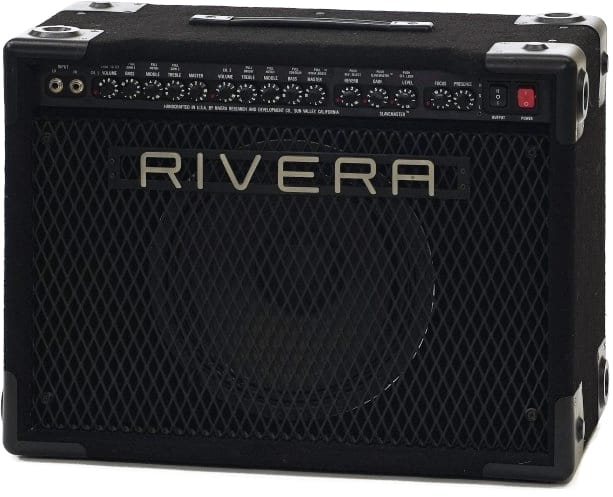
The RIVERA Combo Series has been designed for the professional player who demands a rugged and versatile amplifier, with the advanced features of our renown TBR (Tube Rack) series of amplifiers. The components meet the most stringent computer and military specifications.
The design and construction of the Combo allow you to utilize the latest effects devices (in stereo with the S-120 models) and integrate the amplifier into a system that can be easily transported. It is the culmination of over 20 years of amplifier experience. With moderate care, your Combo will give you years of continuous service.
Quick-start settings
If you didn’t already know it, the size of this owner’s manual tells you Rivera Combo amplifiers have a lot going for them. You should make it a point to spend a few minutes reading the information in this manual to make sure you do not miss something that will cause you a lot of grief later on.
With this said, we understand that you are eager to start playing your new amplifier, and reading a thick owner’s manual is the last thing on your mind.
Therefore, we have put together some settings to help familiarize you with the amplifier and get you off to a quick start. These settings suggestions are meant merely as starting points to help you explore the sonic possibilities of your Rivera Combo.
Enjoy!
| SL VOICING | Vol. 1 | Bass | Mid | Treble | Master | Reverb | SM gain | SM level | Focus | Pres | Power | Output class |
|---|---|---|---|---|---|---|---|---|---|---|---|---|
| Clean Rock | 4 | 4 | 4 | 7+ | 4 | 1-4 | 6 | 6 | P | H | ||
| Plexi Comp | 7 | 4 | 7 | 7+ | 4 | 1-4 | 10 | 5 | P | H | ||
| Tele Edge | 4 | 7+ | 6+ | 8+ | 3-5 | 1-4 | 10 | 6 | P | H | ||
| Death Rays | 10 | 10+ | 5 | 8+ | 2-4 | 1-4 | 8 | 8 | P | H | ||
| Crush Yo Head | 10 | 1+ | 7 | 8+ | 3-5 | 4 | 9 | P | H | |||
| Manic Metal | 10 | 10+ | 1 | 8+ | 3-5 | 1-4 | 10 | 6 | P | H | ||
| Sweet Stuff | 9 | 8 | 6 | 6+ | 3-5 | 1-4 | 8 | 7 | T | H | ||
| SRV Scream | 10 | 8 | 5 | 5+ | 5 | 1-4 | 8 | 5 | P | H | ||
| Hendrix Wild | 9 | 8+ | 4 | 7+ | 3 | 1-4 | 8 | 6 | P | H | ||
| S. Vai Maxi | 9 | 8+ | 6 | 6+ | 3-5 | 8 | 8 | T | H | |||
| R. Rhoads | 10 | 8+ | 1 | 8+ | 3 | 1-4 | 1 | 7 | P | H | ||
| Blue Mack | 7 | 5+ | 6 | 6+ | 3-5 | 10 | 5 | T | H | |||
| Dark Blue | 6 | 5+ | 8 | 4+ | 5 | 10 | 1 | T | H | |||
| Miss Yo Blue | 5 | 10 | 6 | 4+ | 10 | 10 | 3 | T | L | |||
| Metal Modify | 9 | 1+ | 6 | 7+ | 3 | 8 | 4 | 7 | 5 | P | H | |
| Studio Scream | 10 | 5 | 5 | 5+ | 8 | 8 | 3 | 10 | 4 | T | L | |
| Wizard Knobs | 10 | 6+ | 1+ | 5+ | 3 | 3 | 10 | 3 | 10 | 4 | P | L |
| Crank Practice | 10 | 1+ | 10 | 10+ | 5 | 10 | 1 | 10 | 1 | T | L |
Note: Settings shown with a "+" indicate the control should be pulled out.
| M VOICING | Vol. 2 | Treb | Mid | Bass | Master | Reverb | SM gain | SM level | Focus | Pres | Power | Output class |
|---|---|---|---|---|---|---|---|---|---|---|---|---|
| Clean Twin | 3-5 | 7+ | 3+ | 8+ | 10 | 3-5 | 4 | 4 | P | H | ||
| Delux clean | 3-5 | 7+ | 7+ | 5+ | 10 | 1-5 | 4 | 5 | P | H | ||
| Tweed Clean | 4 | 10 | 4 | 3 | 10 | 10 | 7 | T | H | |||
| Fender blue | 7 | 10 | 8 | 5 | 10 | 10 | 8 | T | L | |||
| Funk rhythm | 3 | 10+ | 4+ | 6 | 10 | 1-4 | 1 | 6 | P | H | ||
| P. Jackson Jr. | 3-5 | 10+ | 1+ | 5+ | 10 | 1-4 | 5 | 8 | P | H | ||
| Polyyyton | 3 | 5 | 7 | 10 | 10 | 1-4 | 1 | 3 | P | H | ||
| G. Benson fat | 3 | 5 | 6 | 5+ | 10 | 6 | 6 | T | H | |||
| W. Montgomery | 3 | 4 | 10 | 5+ | 10 | 5 | 5 | T | H | |||
| C. Atkins | 4 | 7+ | 4 | 4 | 7 | 9 | 6 | T | H | |||
| T. May clean | 4 | 8+ | 3+ | 4+ | 6 | 1-4 | 10 | 6 | P | H | ||
| T. May bluz | 8 | 7 | 4 | 1 | 6+ | 1-4 | 10 | 7 | T | L | ||
| Carltone vint | 8 | 7+ | 9+ | 2 | 6+ | 2-4 | 10 | 3 | P | H | ||
| C. Tones clean | 3 | 8+ | 3 | 1+ | 10 | 1-4 | 10 | 6 | P | H | ||
| SRV clean | 3 | 7+ | 5+ | 3+ | 10 | 1-4 | 10 | 6 | P | H | ||
| Old SRV blues | 3-5 | 7 | 3 | 5 | 10 | 7 | 8 | T | H | |||
| Country clean | 3 | 9+ | 1+ | 5+ | 10 | 1-4 | 8 | 6 | P | H | ||
| Eric J. Sweet | 6 | 4 | 10 | 5 | 10 | 1-4 | 5 | 6 | T | H | ||
| Early Cream | 9 | 7 | 1 | 1 | 6+ | 10 | 6 | T | L | |||
| Early Vox | 8 | 8+ | 2+ | 2+ | 6+ | 10 | 6 | T | L | |||
| Super Beatle | 3 | 9+ | 5+ | 6+ | 10 | 1-4 | 1 | 6 | P | H | ||
| Sweet blues | 4 | 9 | 5 | 5 | 10 | 1-4 | 10 | 3 | 1 | 6 | P | L |
| Mobest blues | 8 | 6 | 1+ | 1 | 8 | 10 | 3 | 10 | 4 | T | L | |
| Too blues | 8 | 6 | 5 | 1 | 4+ | 1-4 | 10 | 3 | 10 | 4 | P | L |
Note: Settings shown with a "+" indicate the control should be pulled out.
Input jacks
The nomenclature on the Input jacks comes from the Rivera TBR series amplifiers, which features PCOMP (Pickup COMPensation). The Combo Input jacks allow the musician either to match his pickup output to the input section of the amplifier for the best clean sound, or to mismatch the pickup output for special effects.
Lo
The Lo jack is a high-sensitivity input that matches low output pickups to the Combo preamplifier for best gain. If high output pickups are used in the Lo jack, it will be much easier to overdrive the preamp for harmonic distortion.
Hi
The Hi jack is a low-sensitivity input that attenuates the instrument signal to increase headroom, which makes it easier to play with less preamp distortion, even with high-output pickups.
Effects devices
If you are using an effects device between your instrument and the Combo, the Lo and Hi jacks allow you to match the sensitivity of the preamp to the output of your device.
If your effects device has a guitar-level output (-20 to -4 dB), the Lo jack offers the better match. Most pedal-type effects devices fall into this category.
If your effects device has high-level output (exceeding -4 dB), the Hi jack is more suitable. Most rack-mounted effects fall into this category.
Daisy-chaining
Two (or more) amplifiers can be daisy-chained together by plugging your instrument into the Lo jack, and running a separate instrument cable from the Hi jack to the input jack of the other amplifier. If you operate your Combo this way, be sure to refer to the section on Grounding in Chapter 8, Rear Panel.
Channel 1
Channel 1 has our SL (Super Lead) voicing for the ultimate in harmonics and sustain. It has higher gain than the Channel 2 voicing, yet is still quiet enough to be used in the studio. The SL voicing retains the tonal versatility of Channel 2 except that, due to differences in circuitry, Channel 1 does not need the CONTOUR control.
The SL voicing is related to the family of classic British amplifiers in terms of sustain, compression, and potential distortion.
Volume/Channel select
The VOLUME control regulates preamp volume, and works in conjunction with the MASTER volume control to set level and distortion amount. Setting the VOLUME high and the MASTER low will result in more preamp distortion. Conversely, setting the VOLUME low and the MASTER high will result in a cleaner sound with most of the distortion being generated by the power amp and speakers.
The gain structure of Channel 1 is set up so that as the VOLUME setting is increased the signal is compressed. This eliminates the often harsh sound that occurs when both the preamp and the power amp are driven to extreme distortion. Another way of looking at it is to examine the case in which the MASTER is set at 10. As the VOLUME setting is increased toward 10, the signal will become clipped and compressed to the point that the power amplifier is not being driven full-out. This means that most of the distortion is being generated by the preamp. (For more information on this, see Chapter 3, which discussed the action of the Channel 2 VOLUME control.)
The Channel 1 VOLUME control also features a momentary contact switch with which to change between Channel 1 and Channel 2. Pushing the knob changes from the channel currently in use to the alternate channel (this is the same as pressing the CHANNEL SELECT button on the FS-1 footswitch supplied with your Combo). An LED indicator located next to the VOLUME control indicates which channel is selected.
When the amplifier is first turned on, Channel 2 is automatically selected.
Bass/Gain boost
The BASS control is a passive adjustment that influences timbre contour of the low frequencies, depending on the notch setting. Because the Combo timbre controls are interactive, the effectiveness of the BASS control is reduced as the MIDDLE control is turned up.
The BASS control also incorporates a GAIN switch. Pulling out the BASS control knob increases amplifier gain, making it easier to achieve distortion. Although gain is increased, headroom is preserved to minimize compression (compare with the GAIN boost on the TREBLE control.)
Middle/Notch shift
The MIDDLE control is a passive adjustment that influences the depth of the notch (dip in amplifier response) between the BASS and TREBLE controls. Because the MIDDLE control is passive, it does not boost midrange frequencies. Therefore, increasing the setting of the MIDDLE control fills in the notch but does not cause a bump in frequency response at the notch point, even when turned up to 10.
The interaction among controls gives you more flexibility in fine-tuning the timbre. For example, if the sound has too much bass or treble even with the BASS and TREBLE controls set at 1, you can turn up the MIDDLE control to balance the sound.
The MIDDLE control also incorporates a NOTCH SHIFT switch (a notch is a dip in the frequency response).
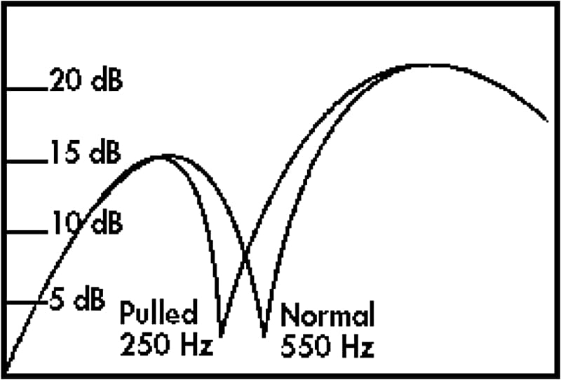
When the control is pushed in (normal position), the notch is at 550 Hz. This is a warm sound typically associated with British amplifiers, and is great for instruments with single-coil pickups.
When the control is pulled out, the notch is shifted to 250 Hz. This provides a good rhythm sound typically associated with American amplifiers, and it is great for Instruments with hum-bucking pickups.
The NOTCH SHIFT is also useful for compensating either for lack of warmth or for excessive boominess in different speakers.
Treble/Gain boost
The TREBLE control Is a passive adjustment that influences timbre contour above the notch point. Because the Treble control is passive, the setting of the Treble control affects the position of the notch. When the Treble control is turned down, the notch point moves to a higher frequency. This translates to a deepening of the perceived bass response and makes the sound less "hollow."
The TREBLE control also incorporates a pull switch for GAIN boost. With the knob pulled out, the instrument signal is slightly compressed, reducing the transient response. This masks the attack of the pick and gives more sustain (compare with the GAIN boost on the BASS control). Between the two Channel 1 boost circuits, it is possible to achieve a wide mix of compression and sustain.
Master
The MASTER control regulates the amplification the power amplifier applies to the preamp signal. On Channel 1, the MASTER is directly after the equalization, with the equalization being post distortion. This allows the equalization to be effective at any MASTER volume and distortion setting.
Channel 2
Channel 2 has our M (Maximum flexibility) voicing for a sweet tone, which also provides good contrast with Channel 1. For rhythm guitar, Channel 2 offers more headroom and a CONTOUR switch (on the BASS control), making it better suited for clean playing.
The M voicing is in the same textural family as classic American amplifiers.
The timbre controls of Channel 2 are arranged in the reverse order of those in Channel 1 as a visual cue to allow you to differentiate between the two more easily.
For basic information about the Channel 2 controls, refer to the description of Channel 1 in Chapter 2. Only the exceptions are noted below.
Volume
The Channel 2 VOLUME control does not compress the signal as the setting is increased. It is therefore easier to drive the power amplifier into full distortion using Channel 2, although Channel 2 does not have as much preamp gain as Channel 1.
Another way of looking at this is to examine the case in which the MASTER is set at 10. As the VOLUME setting is increased, the power amp will be driven into distortion before the preamp begins distorting. With a little experimentation, you will find that power amp distortion is much different sounding than preamp distortion, which is why Rivera amplifiers offer both.
Treble/Bright Boost
The TREBLE control incorporates a BRIGHT switch. The BRIGHT switch provides a nice shiny highlight to the sound instead of the normal screechy high boost normally associated with bright boosts.
The BRIGHT boost is most effective when the VOLUME is set at 6 or below.
Bass/Contour
The Bass control incorporates a Contour switch to provide additional warmth at low levels, compress the mid-range slightly, and increase the highs slightly for a little extra sparkle, as might be needed for rhythm tone enhancement. This contour is introduced before the Master control.
Master/Ninja Boost
The Master control incorporates a special Ninja
boost circuit for a vintage, crunchy texture at low levels. NINJA BOOST increases level and gain without the harshness that characterizes many boost circuits. It allows the addition of drive without affecting timbre. The timbre controls remain active, preserving the dynamic range of the preamp. Additionally, the CONTOUR can be activated to provide warmth when the MASTER is at low levels for a high gain lead sound.
To activate NINJA BOOST, pull out the Channel 2 MASTER. To activate NINJA BOOST from the optional footswitch, make sure that the MASTER control is pushed in, then press the footswitch button. When the MASTER control is pulled out, NINJA BOOST cannot be turned off by the footswitch.
Special Effects
All Combo amplifiers feature an internal reverb, as well as a special footswitchable Slavemaster circuit, a third preamp channel that can be used as a distortion device or additional effects loop.
Reverb
The Combo’s internal Hammond Spring
reverb circuitry has been created for a classic reverb sound: special equalization curves emphasize selected frequencies, while other frequencies are rolled off slightly to provide a clean and intelligible reverb effect. The reverb may be turned on by pressing the REVERB control, or by the pressing the appropriate footswitch button. An LED indicator shows the on/off status.
Slavemaster
SLAVEMASTER is an alternative to running the output of the amplifier through load resistors into effects devices such as digital delays. Although load resistors do work (up to a point), they are an inefficient means to the goal, as they turn an expensive amplifier into a glorified fuzz-tone, generating lots of heat, smoking output transformers, and gobbling up output tubes. SLAVEMASTER duplicates the effect of running a big amplifier through load resistors, without sacrificing reliability (or flexibility). SLAVEMASTER can be used by itself or with its built-in effects loop.
Without Effects
Set your channel tones and levels with SLAVEMASTER off. Next turn on SLAVEMASTER by pressing the SLAVEMASTER GAIN control (or the button on the optional footswitch) and initially set the SLAVEMASTER LEVEL control to about 3. An LED next to the SLAVEMASTER GAIN control shows whether SLAVEMASTER is on or off. (SLAVEMASTER works with either preamp channel.)
Adjust the SLAVEMASTER GAIN control until you reach the desired amount of distortion. Set the SLAVEMASTER LEVEL control to adjust the difference in volume when SLAVEMASTER is turned on.
NOTE: On Mono Combo models, the LED indicator next to the FOCUS control that is unlabeled is the level indicator for the SLAVEMASTER circuit It glows in relationship to how hard SLAVEMASTER is driven. It is activates only when Slavemaster is turned on.
With effects
The Slavemaster circuit includes Send and Return jacks, which allow the use of effects devices with SLAVEMASTER as if it were an effects loop. This means you can use effects devices within the SLAVEMASTER circuit, so that when you kick in Slavemaster, you also kick in additional effects.
As a line-out
If you wish to run the output of the SLAVEMASTER to an external source (amplifier, mixing console, etc.), run a patch cord from the SLAVEMASTER Send jack on the rear panel of the Combo to the desired source. There is no need to use the SLAVEMASTER Return jack in this set-up.
M-Series Amplifiers (M-60/M-100)
M-series amplifiers are available with either 60 Watts of power for recording and smaller gigs, or with 100 Watts for those musicians needing more clean power.
Effects Loop
The Rivera Combo effects loop is active; it is able to drive low input impedance effects devices, and will accept return signals from high or low output source impedance effects pedals. The versatility of the Rivera Combo effects loop can be seen in the many ways of connecting it to external effects. The effects loop has a rear panel SEND LEVEL control and a RETURN LEVEL control for each power amplifier (there are two RETURN LEVEL controls on stereo amplifiers).
The SEND LEVEL control is used to tailor the output of the Combo preamp to the sensitivity of the first device in the effects loop, ideally providing enough signal level to keep the signal-to-noise level low while preventing overload of the input section of the effects device. The RETURN LEVEL control (one for monaural, two for stereo) are most commonly used to balance the return signal of the effects loop, although it can also be used create differences in signal level for special effect.
The effects loop can be turned on either by pressing the SLAVEMASTER LEVEL control or by the effects loop button on the footswitch. An LED indicator shows on/off status. The Send and Return jacks are located below their respective controls on the rear panel.
The rear panel Send jack is always active and may be used as a continuous and variable preamp output, using the rear panel SEND LEVEL control to regulate output level. This signal is post-reverb, post-master volume, and in stereo models pre-Chorus. This means that if you use the effects loop Send jacks as line-outs, you will be able to make use of all preamp controls except for the Chorus (in stereo Combos).
Effects Loop Level
Some effects devices require line level for optimum signal-to-noise ratio. Other devices have less headroom and require instrument-level signal, and will distort easily with line-level signals. With either of these two types of device, however, the SEND LEVEL control is adjusted so the level is at the maximum point possible before overloading the effect or effects chain being used. Before setting the effects SEND LEVEL control, adjust the preamp controls on both channels to desired settings. On the louder channel (if effects are desired), turn on the effects loop and adjust the SEND LEVEL to match your effect or effects chain. If your effects are equipped with level indicators, set the SEND LEVEL so that the effects device is just below the threshold of clipping.
Use the RETURN LEVEL control to adjust the output of the power amp.
If your effects chain Includes a mix of instrument and line-level effects, connect the instrument-level units last in the chain, after the line-level devices. Your last line-level device must have an output level control for this arrangement to work.
Stereo Effects
If the last effects device has more than one output signal ("stereo"), there should also be an output that blends the straight and processed signal together. Connect this output to the Return jack of the Combo.
Other Effects
When no cables are connected to the Combo effects loop jacks, signal from the effects Send jack is sent directly to the effects Return jack. By turning the effects loop on, the effects loop SEND LEVEL and RETURN LEVEL controls will regulate amplifier volume. The most common use of this is to turn up the front panel VOLUME and MASTER controls to get the sound you want, then set amplifier volume using the effects loop SEND LEVEL and RETURN LEVEL controls.
Note: For this to work, there must be nothing plugged into the effects return jacks.
Focus Control
The FOCUS control allows adjustment of amplifier damping. Damping is the ability of the amplifier to control speaker movement. The greater the control (high damping), the closer the movement of the speaker will follow the output waveform from the power amp. The less damping there is, the less control the amplifier has over speaker movement, resulting in speaker movement not directly caused by the output waveform of the power amplifier.
Low FOCUS settings (1 through 4) cause higher damping and tighten up the sound, while higher FOCUS settings (5 through 10) reduce damping and loosen the sound.
The FOCUS control can be used to change the timbre from cold and dry (settings 1 through 4) to warmer with more sparkle (settings 5 through 10). The FOCUS control also allows you to compensate for room acoustics, or to get "your sound" even when playing through borrowed speakers. For example, closed-back cabinets often have a tighter sound than open-back cabinets. The FOCUS control lets you more closely approximate the sound of one when using the other.
Presence control
The PRESENCE control affects power amp equalization, and behaves like a final bright control. Because it is after the preamp section of Combo, any distortion created in the preamp (in conjunction with the VOLUME, MASTER, NINJA BOOST, SLAVEMASTER, etc.), will have its harmonics enhanced by the PRESENCE control.
S-series amplifiers (S-120)
T he S-series amplifiers are sonically the same as our M-series amplifiers, but have two completely separate output stages, as well as a built-in stereo chorus. In regular operation, each power amp drives Its own set of speakers, giving 120 Watts (2 x 60) of power.
Effects Loop
With the exception of an additional RETURN LEVEL control and jack, the effects loop on the stereo Combo works the same as that on the mono Combo. For information on the basic operation of the effects loop, refer to the previous chapter. This chapter will only deal with the differences found in the stereo model Combo.
Binaural Effects
For straight signal from one power amp and effects signal from the other, connect the output of the effect or effects chain to the rear panel Return B jack. This is a very effective way of utilizing monaural pedal effects such as chorus, phaser, flanger, etc., and achieving a "pseudo stereo" effect, i.e. delay in one speaker and direct sound in the other, which gives the impression of a "stereo" effect.
Stereo Effects
Connect one output from the stereo effect to the rear panel Return A jack, and the other to the rear panel Return B jack. The Return level controls can then be used either to adjust the relative loudness of the two power amplifiers.
Chorus
While some chorus amps have pitch bend through one speaker and the straight sound through the other, the chorus in the stereo Combo is a true chorus. In the stereo Combo, the speakers may be far apart with no effect on the perceived chorus sound. The chorus circuit is post effects loop and has stereo inputs to preserve the integrity of full stereo effects devices used in the stereo effects loop.
Speed
The CHORUS SPEED control regulates the rate modulation of the chorus. The Chorus speed control also incorporates a switch for turning the chorus on and off. To activate the Chorus, press the CHORUS SPEED control. The chorus also may be turned on by using the optional FS-3 footswitch. An LED next to the CHORUS SPEED control indicates on-off status.
Depth
CHORUS DEPTH control regulates the strength of the chorus effect. The CHORUS DEPTH control incorporates a PRESENCE switch that combines the FOCUS and PRESENCE control functions of the mono Combo models into a single switch affecting both power amps simultaneously. When pushed in, it is equal to FOCUS set on 1 and PRESENCE set on 2. When pulled out, it is equal to the FOCUS set on 10 and PRESENCE set on 7.
Power amp controls
The tremendous versatility of the Combo does not end at the preamp section. The power amplifier controls give you the flexibility to exactly tune the timbre and output of the Combo to virtually any playing situation.
Standby Switch
The standby switch controls the high voltage (also known as the B+ or HT voltage) supply to the power output tubes, but does not affect the preamp. This allows you to put your amp on standby and continue to use the preamp section, including the Send jack(s) of the effects loop.
By turning the Power on and Standby off, you can warm up the amplifier before applying full voltage. This helps the tubes live longer. Tube life will also be extended if, during breaks, the Standby switch is used to turn the amplifier off
instead of the power switch. This keeps the tubes at a more constant temperature, eliminating the thermal cycling that accelerates aging in tubes, and maintains the amplifier in a constant state of readiness.
The Standby switch has three positions. In the center position, the amplifier is on standby. In the down position (also marked I on the switch and L on the front panel), the amplifier is in the low power mode.
In the up position (also marked II on the switch and H on the front panel), the amplifier is in the high power mode. It is best to stop playing before switching from one mode to the other to protect the circuitry from transient surges. The Standby switch combines with the Power Class switch on the rear panel to give you four distinct power levels.
Power switch
The illuminated Power switch turns the amplifier on and off. It switches both the neutral and the line sides of the mains. The switch is marked 0
for off and I
for on.
Power Class switch (rear panel)
Usually when you buy an amplifier you are stuck with whichever circuit the designer decided on. The POWER CLASS switch allows you to change the fundamental tonal characteristics of your amplifier by giving you the choice between the higher-power pentode class and the lower-power triode class.
The POWER CLASS switch is not primarily designed as a means of changing the power output of the amplifier, however. Its main purpose is to change the tonal characteristics of the amplifier in ways that timbre controls cannot. In the pentode mode, the sound is bright and edgy. In the triode mode, sound is sweet and silky. These changes have to do only with the difference in the way the amplifier processes the signal from your instrument in the power amp stage, therefore your front panel timbre controls function the same under either power class setting.
Rear Panel
With the exception of the instrument input, all other input and output connections are found on the Combo rear panel. The rear panel also contains some less-used controls to reduce front-panel clutter. On S-120 Models, there are two sets of rear power amplifier controls, one for each power amp channel.
AC Connector
The Combo is fitted with a detachable power cord (supplied) which connects to the chassis AC Connector. The power cord has an IEC female connector on one end and a male mains connector on the other end. This cord is supplied specifically to accommodate the different safety and electrical code requirements of individual countries.
Be sure to use a grounded electrical mains power supply socket whenever possible. These have a grounding pin in addition to the normal line and neutral pin. The power cord supplied with your Combo has a 3-pin type plug. Do not cut off or damage the ground pin. If the available electrical outlet is of the older 2-pin type, use a suitable ground lift adapter.
USA, Canada, and Japan share a common CSA/UL style cord. Most of Europe and Scandinavia utilize a Euro plug and have a SEMKO/VDE style cord. Australia uses a different style plug, as does England. In the event that the power cord requires replacement, replace with the same type power cord. Consult your Rivera dealer for further information.
AC Line Fuses
AC line fuses protect your amplifier from damage due to shorts, momentary surges, and defective power tubes. In the event of fuse failure, please replace with the same type fuse.
If your fuse repeatedly blows, please refer your amp to your local Rivera dealer or contact us at (818) 833-7066 for further service assistance.
| Model | 100V | 120V | 220V* |
|---|---|---|---|
| M-60 | 3A Slo-Blo | 3A Slo-Blo | T1.6A |
| M-100 | 5A Slo-Blo | 4A Slo-Blo | T2A |
| S-120 | 5A Slo-Blo | 4A Slo-Blo | T2A |
*5×20 mm
Polarity Switch (100/120V)
The POLARITY (ground) switch is for selecting a low current chassis ground (earth) alternative to reduce grounding-related hum noise. Use the position that sounds the most quiet. When using the Combo in combination with other amplifiers or electrical appliances in the same rack, or in a situation where a signal cord goes to and/or from the Combo and another mains-connected amplifier, appliance, or chassis, and it is also equipped with a polarity switch, switch it to the center position if possible, and set the POLARITY switch on your Combo in the position that sounds most quiet.
In the event that there is a ground loop hum due to redundant mains grounds (where more than one amplifier, appliance, or chassis are connected to each other in some manner, and each unit in question has a AC ground connection), try using ground lift adapters on the other units one-by-one until the hum is reduced. If this does not help, consult your local RIVERA dealer or contact the RIVERA factory for further assistance.
AC Voltage Selector (220V)
A VOLTAGE SELECTOR is found in place of the POLARITY switch on RIVERA amplifiers built for export markets. It allows the amplifier to be switched for 220 VAC or 240 VAC 50/60 Hz AC voltages.
For England, Australia, and any country where the mains voltage is 230 or 250 VAC, use the 240 VAC position. For most of Europe and Scandinavia where the mains voltage is 210 or 220 VAC, use the 220 VAC position. In countries using 127 VAC you will need a 120 VAC version of Combo. If your local voltages are none of the above, contact the RIVERA factory.
NOTE: Before adjusting the Mains Selector switch, be sure the amplifier is disconnected from the mains supply and is switched off Consult your local electrical authorities for mains voltage information in your area.
HT Fuse
The power amplifier circuits have their own fuse for protecting the output section from short circuits and transient current peaks that exceed the normal current draw. These conditions are usually caused by a bad tube.
When a short circuit or transient peak causes the fuse to blow, the output tubes should be checked, and replaced if necessary.
Repeated blowing of this fuse is a clear indicator of a defective output tube.
| Model | 100 V, 120 V | 220 V* |
|---|---|---|
| M-60 | .5A Slo-Blo | T.63 Ma |
| M-100 | 1A Slo-Blo | T1A |
*5×20 mm
Speaker output jacks
Each power amp is equipped with two speaker jacks connected in parallel. Speaker 1 jacks are equipped with an internal safety switch which turns the power amp off if no speaker plug is inserted. This means you must use the Speaker 1 jack before you can use the Speaker 2 jack.
WARNING: If you have a speaker cord plugged into Speaker Jack 1, the power amp is fully operational. Do not operate your combo without a proper speaker load.
Stereo Combos have two Speaker 1 jacks and two Speaker 2 jacks. For stereo operation, both Speaker 1 jacks are used. If you wish to run a stereo Combo in monaural (for reduced output, for example), you may either unplug one speaker plug, or transfer it from one side to the other side. Note that when connecting additional speakers to any power amp, you must ensure that the total speaker impedance is correct for the impedance setting.
We do not recommend using any of our Combo amplifiers in a slaving system whereby the power amp section will be on high sustained and continuous power. The Combo is ventilated through passive convection, and excessive heat may build up shortening the tube life. However, with the SLAVEMASTER feature operation of Combo in a typical slaving system is unnecessary.
Direct Out jacks
Each power amp is also equipped with a low-impedance Direct Out jack suitable for PA mixers, tape recorders, and other power amps. This signal is padded down from the speaker signal and is capable of up to line-level output. If the amp is on standby or the Speaker 1 jack is not used, the Direct Out jack is inoperative.
When running the signal from the Direct Out jack to a mixer, it is best to roll off the frequency response above 8kHz.
Impedance selector
Each power amplifier is equipped with an IMPEDANCE SELECTOR switch. This allows the amplifier to properly match the load of the speaker(s) being used, so that full output power is available at any one of the three load impedance settings (4, 8, and 16 Ohms). Set the IMPEDANCE SELECTOR switch for the total impedance load of the speaker connected to both jacks combined.
NOTE: Adjust the IMPEDANCE SELECTOR switches to the proper impedance load setting before plugging in the speakers and turning on the amplifier.
For Combo models equipped with internal speakers, the IMPEDANCE SELECTOR switch is pre-set from the factory to the correct setting.
On Stereo Combos, you may set one IMPEDANCE SELECTOR switch to match the impedance of one set of speakers and the other IMPEDANCE SELECTOR switch at a different impedance to match another set of speakers, if necessary.
RIVERA speaker cabinets are equipped with 8 Ohm speakers (either stock, Celestion, JBL, or Electro-Voice speakers) and are wired for either stereo or mono operation.
| Combo model | Amp 1 | Amp 2 |
|---|---|---|
| Mono 1-12 | 8 ohms | n/a |
| Mono 2-10 | 4 Ohms | n/a |
| Mono 2-12 | 4 Ohms | n/a |
| Mono 4-10 | 8 Ohms | n/a |
| Stereo 2-10 | 8 Ohms | 8 Ohms |
| Stereo 2-12 | 8 Ohms | 8 Ohms |
| Stereo 4-10 | 4 Ohms | 4 Ohms |
Most single speakers are 8 ohms. If two of them are connected to the same power amplifier (one in Speaker 1 and the other in Speaker 2), the selector should be set at 4 Ohms.
External speakers
External speakers cannot be used with a Mono 2-10, Mono 2-12, or Stereo 4-10 Combo unless you first either disconnect the internal speakers or rewire the internal speakers from parallel to series. This increases the impedances listed above from 4 Ohms to 16 Ohms. Note that if you make this change you must also change the setting of the IMPEDANCE SELECTOR switch.
If you desire a total internal speaker impedance of 8 Ohms, you must replace the supplied speakers with either 4 Ohm or 16 Ohm speakers, wiring the 4 Ohm speakers in series, or the 16 Ohm speakers in parallel to achieve 8 Ohms total impedance.
| Speaker | Wiring | Mono | Stereo |
|---|---|---|---|
| C210 | Parallel | 4 Ohms | 8 Ohms |
| C212 | Parallel | 4 Ohms | 8 Ohms |
| C410 | Series/parallel | 8 Ohms | 16 Ohms |
| Q-Cab | Parallel | 4 Ohms | 8 Ohms |
| 412T/412B | Series/parallel | 8 Ohms | 16 Ohms |
Footswitch jack
The RIVERA™ FS-1 three function Illuminated footswitch (supplied) comes with a five-meter shielded 8-conductor cable. The connectors are 8-pin DIN plugs and jacks.
When FS-1 is connected to the Footswitch 1 jack, channel, reverb, and effects loop selection can be made through the footswitch. LED indicators on the footswitch, which correspond to their counterparts on the front panel, indicate when a function has been turned on.
When the FS-1 is connected to the Footswitch 2 jack, SLAVEMASTER, NINJA BOOST, and (in stereo models) CHORUS are footswitchable.
Additionally, there is an optional FS-2 footswitch available for monaural Combos for switching SLAVEMASTER and NINJA BOOST, and an FS-3 footswitch available for stereo Combos for switching SLAVEMASTER, NINJA BOOST, and CHORUS.
Hum Adjust pot
The HUM ADJUST pot is for use by qualified technicians only. Uncalibrated adjustments will degrade the sound of your amplifier.
Maintenance
Each Rivera Combo has been designed and built with the professional musician in mind. The highest quality parts and materials have been used throughout this unit. In the unlikely event of a problem, some useful service information is provided.
Care and cleaning
Most Combo amplifiers are covered in rugged black Nyflex carpet. Some special order amplifiers are covered in black Tolex vinyl.
It is easy to clean by using a brush and brushing the nap of the carpet whenever necessary.
For Combo units covered in Tolex, clean the surface with a slightly damp cloth.
Be careful not to expose the Combo to any liquids or moisture as they may get into the chassis and possibly cause a fire or shock hazard.
If the control knobs become dirty, they may be pulled off gently and washed in a mild dish washing soap solution. Be sure to rinse and dry the knobs carefully before reinstalling them.
The front control panel can also be wiped down with a slight damp cloth to remove fingerprints.
WARNING: Do not remove speaker protective grill without wearing suitable gloves. Grill edges may be sharp and result in cuts to the skin if not handled properly.
Tube Changes
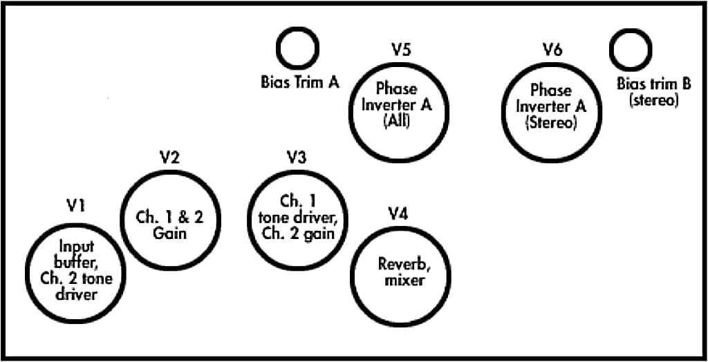
It is normal for tubes to wear with age. The tubes and their function and physical location are shown on an accompanying chart.
WARNING: Before attempting to change tubes, be sure that the amplifier is unplugged from the power supply, that the tubes have cooled down, and that no metallic objects come in contact with the pins of the tube sockets. Failure to observe these precautions will result in skin burns and shock hazard.
As it is difficult to see the pin orientation of the preamp tubes (9 pin miniature), it may be a more convenient to turn the amplifier upside down to aid in seeing the tube socket location and orientation.
If other output tubes are used in place of EL-34s, the power output will vary and timbre change. However, the preamp and phase inverter tubes are 12AX7As, 7025s, ECC83s, or 6681s, which are all similar twin triode hi-mu miniature 9 pin tubes and are sonically very similar.
A word about tube quality: There are only a handful of tube manufacturers worldwide, and there are no Western European or British companies manufacturing any longer. Other companies purchase their tubes from the same sources we do.
Every tube you buy from us, whether in an amplifier or as a replacement part, has been hand-selected for low hum noise, low microphonics, and high gain. After a burn-in period, tubes that fail to meet our rigid specifications are either discarded or sold to other shops. If you wish to purchase replacement tubes from us directly, we will be pleased to assist you. Contact the factory for price and ordering information.
WARNING: Never ever use Chinese EL34s, 6550s, or 6L6GCs. They are mechanically unstable and will shorten the life of your amplifier.
Testing preamp tubes
Because of the amount of gain that they contribute to the signal, the preamp tubes are most sensitive to noise. We hand-test all tubes for noise, grading them accordingly. Tubes marked "10+" are the quietest, which tubes marked "phase inverter" are less quiet, but are still fine as phase inverters, which are less sensitive to noise.
Tested and graded tubes are available from Rivera Research, but with a little practice you can test tubes yourself.
- Be prepared to discard a lot of tubes.
- Install a tube to be tested in the second tube socket (V2). This is the most sensitive position, so it is the best place in which to test for noise.
- Turn off the effects loop.
- Set the TREBLE and BASS at 10 for both channels. Turn the MIDDLE to 1 for both channels.
- Set the VOLUME control for both channels on 1.
- Turn the MASTER to 10 for both channels. Pull the Channel 2 MASTER for NINJA BOOST. Pull the Channel 1 GAIN 2.
- With the amplifier turned on and warmed up, tap on the tube with your finger. Switch back and forth between channels to test both halves of each tube.
- At first, all the tubes you test will sound noisy. As you get used to listening to tubes, however, you will learn what constitutes a quiet tube and what a noisy tube sounds like.
- Label the tubes for later reference.
Testing power tubes
We also hand-test, grade, and match all power amp tubes for gain. When a power tube fails, however, it is not usually a gain or noise-related problem (although power tubes can physically deteriorate to the point at which they rattle internally). The most common power tube failure is due to internal short circuits.
Rivera Research sells tested, graded, and matched sets of tubes. Tubes are rated between 6 and 14, with 6 being the lowest gain but longest-lived tubes, and 14 being the highest gain but shortest-lived tubes. Generally speaking, when you purchase tubes from us, they will range between 8 and 12 (or all-around good gain and life expectancy.
Even the best tubes go bad, however, so it is important to be able to test power tubes in the field. In any pair of tubes, usually one will fail at a time. If you can determine which tube is still good, you can continue to use it.
- If a power tubes has shorted, the fuse will be blown. Remove power from the amplifier and replace the fuse before continuing.
- Remove all the power tubes.
- Replace the tubes one at a time. When the fuse blows (or the tube glows cherry red, indicating an internal short), you have found the bad tube.
- Replace the bad tube with a known good tube.
Bias Voltages
On the main circuit board there Is a bias adjustment trim potentiometer for each power amp. The bias will rarely need to be adjusted under normal circumstances. NOTE: Removing the chassis from the cabinet exposes extremely dangerous high voltages. Refer all servicing to qualified personnel. No user serviceable parts inside. The following information is provided for the benefit of qualified service personnel only.
To open the amplifier:
- Remove the four Phillips screws that hold the back cabinet panel.
- Remove the top five Phillips screws that hold the chassis in place.
- Remove the reverb pan grounding wire from the back of the chassis, and the reverb signal cables from the bottom side of the chassis.
- Slide the chassis out of the cabinet. It may be necessary to remove the front control panel held in place by five Allen head cap screws to ease rear movement of the chassis.
If the bias adjustment pot does not have enough range, the 18k resistor next to the adjustment pot can be replaced with a higher value for Increased bias range.
| Tube | Voltage |
|---|---|
| 6CA7 USA | 39 VDC |
| 6L6GC USA | 45 VDC |
| 6550A USA | 52 VDC |
| EL-34 (American) | 39 VDC |
| EL-34 (English or German) | 37 VDC |
| KT-77 | 39 VDC |
Measure bias with amplifier at idle, with nominal line voltage.
Never use Chinese EL34s, 6550s, or 6L6GCs.
Internal Fuses
On the power supply circuit board, there are fuse holders for 5×20 fuses. B+ fuses (Semko only) are T1.6A Slo-Blo; the low voltage fuses are T1A. The bias supply fuse is supplied only to Scandinavian markets and is T100mA. Scandinavia models also have two filament fuses mounted on the chassis. The filament fuses for both the power amp and the preamp are T8As.
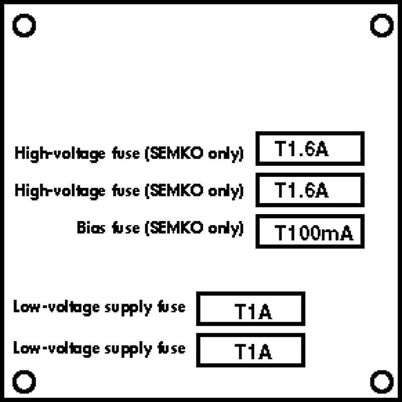
NOTE: Always replace the fuse with the same type and value. Do not use higher current-value fuses.
Fuses normally blow for a reason. If one or both of the B+ fuses blows, this is probably caused by a shorted output tube. You should change the tubes as a precaution. See the accompanying diagram for location of fuses on the power amp printed circuit board.
The power output stage has protection devices on the output transformer. These devices assist Combos in coping with open loads and temporary transients.
Internal components
There are a total of four circuit boards with components in the M-60 and M-100 models, with five circuit Boards in the S-120 models.
- Motherboard, which has logic, preamp, power amp and reverb.
- Power supply board, for all power supply filtering and rectification.
- Effects loop board. All effects loop circuitry except the relay.
- Phase inverter/ chorus control board, with the SPEED and INTENSITY or FOCUS and PRESENCE controls.
- Chorus board (S-120 models only).
All ICs are mounted on sockets. All LEDs are driven by transistors and each LED has its own current-limiting resistor. The footswitch circuit has low-current, one-shot Schmitt Trigger inputs, and all are latched. The switches are momentary contact, and are normally open. Each LED has its own return line, and this line can function for parity if necessary. Ground is common for all logic.
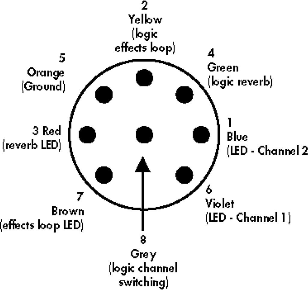
See the accompanying diagram for the pin-out of the footswitch connector. Maximum recommended footswitch cable length is 25 meters. Use Mogami #W2789 or equivalent for footswitch, patch, or extension cables.
Channel switching (in the audio path) is accomplished with optically coupled devices. Reverb is switched by a special high voltage optical switch. The effects loop is switched by a latched microminiature, military-grade relay, with full (zero ohm) bypass on the effects loop returns.
The primary filter capacitors for all power supply circuits are 105 degrees Celsius military grade. All internal hookup wire used for point to point connections is a minimum 105 degrees Celsius, 600V. Silver plated copper Teflon insulated wire is used on many point-to-point connections. Most signal conducting wires are of the shielded type. All large electronic components are glued to the circuit boards with a special vinyl adhesive. If in the unlikely case that any of the components need replacing, please use 3M Weather Strip Adhesive to affix the components to the printed circuit board. Do not use silicone sealants as they will eventually cause failure of soldered electrical connections.
Because we took great pains to choose and utilize the best parts we can find, please utilize original RIVERA spare parts whenever possible.
Auxiliary cooling
The Combo was designed for field retrofitting of a Molex connector for the connection of a fan. If you are going to be using the Combo in high ambient temperatures, a fan is recommended.
The optional field retrofit fan kit consists of the following:
1 4-inch 120V fan
1 Mounting bracket
1 Molex plug pre-wired
1 Molex Socket Pre wired with Fan Harness
4 #8 Phillips truss head wood screws
4 #6-32×½-inch Phillips truss head machine screws
4 #6-32 Kep nuts
4 #6 flat washers
NOTE: Please have this kit installed by a qualified technician as installation entails wiring the connectors to internal circuits of Combo.
Specifications
Because we strive to build for you the highest quality product, we reserve the right to change specifications of our products without prior notice.
Preamplifier
Input impedance: 1 meg ohm
Channel 1 EQ: 3 band passive with variable notch and dual-stage boost circuits.
Channel 2 EQ: 3 band passive, with variable notch and loudness contour, and special equalized NINJA BOOST circuit.
Tubes: 12AX7A, ECC83, 6681, or 7025
Switching logic: CMOS
Effects Loop
Send impedance: 600 ohm
Send level max: +20dBV
Return impedance (x2): 250k ohm
Return signal level max: +30dBV
Slavemaster Loop
Send Impedance: 600 ohm
Return Impedance: 330K ohm
Power Amplifier
Output impedance: 4, 8, 16 Ohm
Tubes: EL34
Speaker Jacks: 2 (parallel)
Line out impedance: 330 ohm
Phase inverter: 12AX7A, ECC83, 6681, or 7025
Power Requirements
CSA North American model: 120VAC 50/60Hz
MITI Japan model: 100VAC 50/60Hz
SEMKO/VDE/Australia model: 220/240VAC 50/60Hz
General
Weight: See chart
Size: See chart
Maximum chassis temperature rise SEMKO model: 70 degrees Celsius (total)
Accessories
Mains power cord, primary footswitch, owners manual, optional footswitch.
| Pentode | Triode | |||
|---|---|---|---|---|
| Model | High | Low | High | Low |
| M-60 | 60 | 15 | 30 | 8 |
| M-100 | 100 | 25 | 50 | 10 |
| S-120 | 60 | 15 | 30 | 8 |
| Model | Idle | Full power |
|---|---|---|
| M-60 | 90 Watts | 300 Watts |
| M-100 | 150 Watts | 440 Watts |
| S-120 | 150 Watts | 440 Watts |
Warranty
Subject to the Obligations and Exclusions found below, this Rivera Research product is warranted against manufacturing defects in material and workmanship for the period of one (1) year from the date of purchase, with the exception of the tubes, which carry no warranty, and loudspeaker drivers, which are covered for 90 days.
The warranty period commences on the date of purchase by the original user. Performance under this warranty must be obtained at one of the following; an RRD Authorized Service Station, by returning the unit to the RRD factory with prior authorization, or (in countries outside of the United States) by a representative RRD distributor. A list of RRD Authorized Service Stations can be obtained from Rivera Research and Development Company, 13310 Ralston Ave., Sylmar, CA 91342, USA, ATTN: Warranty Service. Telephone (818) 833-7066, telefacsimile (818) 833-9656.
Obligations
- This warranty will be honored only on the presentation of the original proof of purchase.
- Transportation of the product to and from the service station or RRD factory is the responsibility of the user unless specifically stated otherwise in this warranty.
Exclusions
- This warranty shall not cover adjustment of customer-operated controls as explained in the appropriate model’s instruction manual, or products that have been altered, replaced, or have missing serial numbers.
- This warranty shall not apply to the appearance of accessory items including, but not limited to, cabinets, cabinet parts, or knobs.
- This warranty does not apply to uncrating, setup, installation, or the removal and reinstallation of products for repair.
- This warranty shall not apply to repairs or replacements necessitated by any cause beyond the control of RRD including, but not limited to, any malfunction, defects, or failure caused by or resulting from unauthorized service or parts, damaged or broken tubes, improper maintenance, modification or repair for the user, abuse, misuse, neglect, accident, fire, flood or other Acts of God, or incorrect line voltage.
- This warranty shall not apply to any loudspeaker drivers that have been damaged due to thermal destruction, or physical destruction such as moisture, rips, tears, shock, or transport.
- Responsibility for the repair of any RRD product sold outside of US boundaries is borne by the RRD representative in that particular country or territory. Also, the warranty term and conditions may be different from those stated above. Please contact the RRD distributor or dealer in your country for more information.
The foregoing is in lieu of all other expressed warranties, and RRD does not authorize any party to assume for it any other obligation or liability. In no event shall RRD be liable for special or consequential damages arising from the use of this product, or for any delay in the performance of this warranty due to causes beyond our control. Some states do not allow limitations on how long an implied warranty lasts and/or do not allow the exclusion or limitation of consequential damages, so the above limitations on implied warranty and consequential damages may not apply to you. This warranty gives you specific legal rights. You may have other rights that vary from state to state.
RIVERA™ PRODUCTS ARE HANDCRAFTED IN CALIFORNIA, U.S.A.